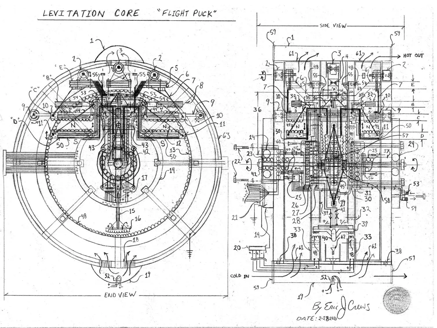
The “Levitation Core” is an electromagnetic device intended to produce lift using electromagnetism. The design then may assist aircraft in stable flight preventing crashes. Letter “B” is the adjustable attractant electromagnet, letter “C” is the fixed position ( upon rotational carriage) electromagnetic electromagnet, letter “D” is the adjustable repellent electromagnet. The electromagnets adjust by hydraulic pressure and electromagnetic “pressure” via the linear electric motor (solenoid)… Letters “B” and letter “D” move in tandem by hydraulic fluid pressure and the core linear electric motor (solenoid). Letters “C” and letter “E” are tandem stationary in reference to each other however able to circular rotate to change the displacement force vector. Letter “E” mounts the roller wheels then causing uplift upon the “hull” / outer casing. The design system could be useful in asteroid control to avoid an asteroid impacting the Earth.
Parts List
1. hot air exhaust duct
2. top plate roller wheel
3. crown wheel assembly
4. crown wheel brace / bracket assembly
5. top plate rubber bushing
6. top plate metal structural support “frame”
7. tension connecting support rod
8. lift plate attractant electromagnetic electromagnets
9. “fixed” plate roller wheel support (upward force contact surface)
10. fixed plate electromagnet
11. rise bar electromagnetic (repellent magnetic poles aligned to the “fixed plate” that has rigid connection to the roller wheel assembly pushing upward)
12. rise bar “connection rod” gives additional structural support to the frame of the rise bar
13. stator / field coil
14. thru bore electrical current slip ring – multi track electricity transference slip ring
15. electric motor armature extension rod
16. electric motor armature – reversible current direction allows for force displacement to change vector , mounted to the base of the opposed piston system with the mounting bracket affixed and fastened by letter “H” ( sum of four mounting points “about a square”) final spacing between the armature and field coil then always allowing free travel distance so that the armature not to “crash” into the stator / field coil factoring the travel of the opposed piston assembly
17. core piston assembly multi wire bus clip mounting bracket
18. hull support bracket
19. cold forced air duct
20. field coil / stator electrical power feed multi wire “bus” wire connector
21. electrical multi wire “bus” wire bus connector
22. bolts
23. spindle (core shaft) sealed bearing races (sealed lubrication)
24. main bearings (sealed lubrication)
25. electronics and electricity control to manage the internal systems of the levitation core – electric switching / electricity control electronics
26. electric motor positional sensor – allows for the information to position the force vector displacement
27. thru bore electricity slip ring – multi track electricity transference slip ring
28. core support bearing race thru bore current transfer slip ring changes the fluid direction via the opposed piston assembly electric hydraulic fluid flow switch – the electricity transference slip ring with sealed lubrication rotates tandem with hydraulic fluid transference slip ring for the core dual opposed hydraulic piston system oil flow switch (hydraulic fluid transference from stationary position to circular rotation for the fluid exhaust and fluid in flow)
29. electric hydraulic fluid flow switch box – controls hydraulic fluid pressure flow direction an contains the hydraulic fluid jack valve position controls the fluid switching for number 36 and letter “X”… a “multi port electric hydraulic fluid valve control box” with compression couplings for the attached oil (hydraulic fluid) flow pipes
30. core support bearing race sealed lubrication with hydraulic fluid transference for the core dual opposed hydraulic piston system (hydraulic fluid transference from stationary position to circular rotation for the fluid exhaust and fluid in flow
31. core support bearing race sealed lubrication with hydraulic fluid transference for the core dual opposed hydraulic piston system (hydraulic fluid transference from stationary position to circular rotation for the fluid exhaust and fluid in flow
32. lift magnet height
33. field coil / stator for the positional electric motor mounting frame
34. field coil / stator for the positional electric motor mounting frame
35. reverse circular fillet support union bracket
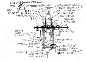
36. rise piston of the opposed piston assembly – The “opposed piston” is aligned so that there are two diametrically opposed pistons with the rise piston then lifting the rise bar letter “D” and in the opposed position or “inverted” position the opposed hydraulic piston then causing uplift upon the casing of the rise piston, number 36, to nullify the reaction force produced. This cancels the equal but opposite force reaction in the force equation then with the system mounted not encumbering the core spindle or it’s outer spinning casing sending the reactant force horizontal within the shear of the laminate “shear plate” letter “Q”.
37. main mounting spindle “mounting casing” for the core spindle
38. roller wheel guide track
39. electric motor armature (reversible direction capacity)
40. counter weight pendulum
41. armature connecting rod electricity conduit
42. core spindle “core shaft ” end nut
43. mounting bore fixed plate to the solenoid stator field coil
44. tension support connecting “rod”
45. opposed rise piston system mounting bracket
46. rise bar hydraulic piston union bushing / bolt system – raises the lift bar letter “D”
47. expansion turnbuckle
48. field coil / stator for the positional electric motor
49. linear motor armature internal solenoid armature – causes rise of the lift bar letter “D” in a constantly adjusting fashion so that the decompression of the “magnetic bubble” then will “reset” also with the lift effect of the attracting electromagnets. The inertia then compensated for with the changing vertical velocity by the adjustment of electricity level in the solenoid that is also using the hydraulic piston system as a “dampener” like an adjustable shock absorption system that is constantly adjusting along with the core solenoid, number 49 and number 51. Think in terms of a “resetting slide jack” that “resets” is base lift point. The core solenoid acts as the “system rise throttle”… and is guided by tracks with the stator field coil containing roller bearings ( sum of 3 about 360 degrees) The solenoid core armature then tandem union affixed with number 50 that also uses guide bearings.
50. rise bar support frame raised by the hydraulic piston, number 36 and the core solenoid (numbers 49 and number 51 with 49 rising upward by electricity the “lift throttle”) – number 50’s support frame also increasing the distance between the attracting electromagnets letter “B” and fixed position letter “C’s” top surface when the core linear motor ( solenoid ), is electrified.
51. linear motor field coil (solenoid field coil) stator / field coil then docking to the core spindle outer casing using compressing cap
52. thermostat and temperature sensor
53. hydraulic fluid compression coupling
54. hydraulic fluid compression coupling
55. top plate and fixed plate connection support rigid support
56. rise piston and lift bar connecting bracket bolt / nut union
57. floating rise piston mounting bracket a high tension hard plate (surpasses the maximum shear strength referencing the magnetic repellent force between letters “C” and “D”). the mounting bracket is a laminate compression with vertical resistance of metal and carbon graphite epoxy cured in an enclave
58. floating piston mounting bearing system
59. rubber bushing compression gasket
60. main spindle
61. vents
62. flat head screw
63. outer hull (flat head screw union mates three roller wheel tracks (left track for number 2 and number 9, center roller wheel guide track for number 3 and right for numbers 2 and 9).
Letter “A” is an open hole in the fixed plate structural component
Letter “B” is lift deck attractant electromagnetic electromagnets ( magnetic south pole may be magnetically insulated – sealed south pole)
Letter “C” is the fixed plate electromagnets hard locked to the roller wheel assembly via connection system produced by number 55
Letter “D” is the rise bar electromagnetic electromagnet
Letter “E” is the crown plate roller wheel mounting plate
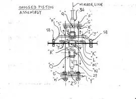
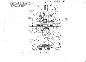
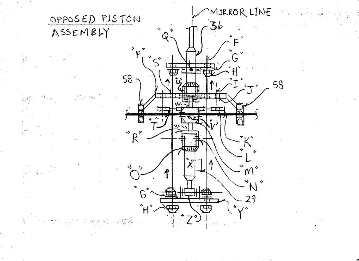
Below please find the opposed piston assembly then incorporated within this design. The opposed piston assembly assist in nullification of reactant force produced from repellent electromagnetism in letters “C” and “D”. The compression rods act upon the base of number 36 pushing upward by the inverted piston (opposed piston by hydraulic fluid suction) then held in place by the tension rods mounting plates. The connection rod plate is welded and bolted to the opposed piston cup. The compression rods then, the sum of four, are positioned toward the corners of the square shape mounting plates letter “Q” (number 36) and letter “Y”.
The “base cup” ( letter “U”), then is bolt secured to number 36 and letter “X”, via bolts at 60 degree interval about 360 degrees (sum of six bolts). A guide sleeve then may also surround the connecting rod also bolted to number 36 to ensure the stability of the base cup. The core spindle then passing thru a force cage ( letter “M”) structural support cage within the piston assembly. The piston assembly “force cage” not to effect the spindle by the compression rods vertical motion…. The “shear plate” ( letter “Q”), then exceeding the magnetic repellent pressure induced between letters “C” and letter “D”), while the compression rod is causing expansion to “zero” the magnetic repellent “pressure” upon the bearing races upon the system. The bearings, number 58 then only carry the actual weight of the opposed piston assembly and attached components not the “pressure” from the electromagnets.
Opposed Piston Assembly Parts List
Letter “F” = threaded compression rod letter “F” sum of four positioned in the corners of a square
Letter “G” = flat washer
Letter “H” = adjustable lock nut
Letter “I” = bolt suspension assembly
Letter “J” = floating mount plate (“carries” the weight of the the assembly not the magnetic repellent “pressure” produced between letters “C” and letter “D”)
Letter “K” = mounting plate
Letter “L” = spindle cage mounting support
Letter “M” = spindle cage “force carrier” yet does not effect the spindle through shaft
Letter “N” = opposed hydraulic piston – uses suction to cause opposed pressure
Letter “O” = piston locking “cup”
Letter “P” = floating mounting “bracket”
Letter “Q” = shear force laminate plate mounts to the outer casing of number 36. The “plate” exceeds the magnetic repellent force between letters “C” and letter “D” via compression of the rods letter “F” and the material selection of the plate then by it’s resistant “shear force”
Letter “R” = opposed piston locking mounting cup assembly contains connection rod to the force cage letter “M”
Letter “S” = expansion rod (letter “F”) through bore hole
Letter “T” = mounting plate
Letter “U” = number 36 mounting threaded bore bolts the “cup” to the piston ( the mounting “cup” has a slide distance capacity to then slightly raise and lower upon the “floating” opposed piston assembly mounting system – contains rubber compression bushing)
Letter “V” = spindle open bore holes
Letter “W” = connection rod
Letter “X” = opposed hydraulic piston by hydraulic suction
Letter “Y” = high strength steel flat plate
Letter “Z” = opposed hydraulic piston “piston rod” to “piston cup” bolt assembly contains rubber bushing – causes counter force compressing the rods
* Note – to control unwanted electrical inductance produced from high magnetic field a “plasma box” will be incorporated into the system governing electronics so that no chance of an unwanted electrical shock hazard exist within the design. A plasma box is a pair of step down electricity transformers sealed in inert noble gas such as argon to de-energize the components that might become electrified by inductance. A “plasma box” acts as an artificial electrical ground to keep the casing “hull” safe and free of electrical conductivity.
* Note – letters “E” and letter “C” are stationary in reference to each other locked by number 55 support rod system
* Note – letters “B” and letter “D” move in tandem
* Note – the core solenoid number 49 and number 51 assist in the rise rack number 50 to then raise and lower by electric current intensity along with the hydraulic piston, number 36
* Note – letter “C” has bore holes allowing free vertical travel of number 50 (number 50 sum of six rods about 360 degrees equally spaced) containing alignment sealed lubrication guide bearings in the bore holes of letter “C”
* Note – high density high voltage supplied by a perpetual motion fuel less “draft accelerator” fuel less high voltage generator. The following link then the generator design Electric Water Propulsion with the number 30 in the water propulsion system then altered to become a hydraulic fluid pump to then be used for the hydraulic piston system, number 36 in the main drafting upon this link..
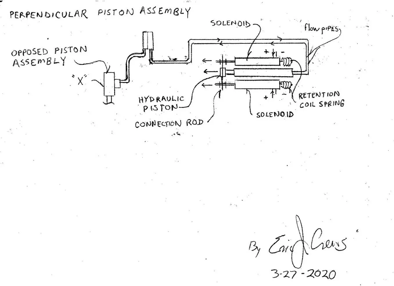
* Note – The negative fluid pressure for letter “X” then obtained by an additional hydraulic piston system and solenoid assembly sum of four (two actuated simultaneously two solenoid on stand by as a safety system). The hydraulic piston system then being force expanded by solenoids with a tension coil spring retainer to act as a safety system. The coil spring will “relax” as the solenoid expands the additional hydraulic piston pulling fluid from letter “X”.
The system contains negative pressure sensor. The sensor will then provide information to then work in tandem with the hydraulic expansion of number 36 and the electricity control system for the core solenoid and the electromagnetic electromagnets to provide stable control by the pilot. The negative fluid pressure producing solenoids and hydraulic piston “expansion” assembly then mounted perpendicular to the vertical lift “plane” to “off set” (nullify) the total system “force” static in the math.
* Note – in concept this design is similar to an aircraft wing then producing lift by lower “pressure” upon the top of the wing… and in this design the lower pressure then being the magnetic attracting electromagnets. The “lift” decompresses the magnetic compression “bubble” between the repellent magnets then causing the fixed disk “letter “C” to rise causing the roller wheel assembly to push upward at which point the core solenoid increases it’s height causing the cycle to repeat in rapid succession.
The sequence then like a “lift jack” but with the electronic “power” (electricity), control circuits not to cause rapid vibration as the upper “lift” magnets are then attracting electromagnets and then the electrical control circuits (throttle), will then increase to “total lift” power level… by increasing the pressure bubble repellent force by proximity and magnetic intensity level causing rise like a under carriage
air cushion of an air flotation hover craft.
* Note – the design system may be applied to the “lift bar” assembly in Lark ( Land Air Reconnaissance Kraft)
* Note – Since this design concept is a flight system reduction of weight and strength of the construction material are a critical factors.
Electromagnets are generally heavy so to reduce the physical weight of the magnet a open hole honeycomb cooling structure may be used to then reduce the total weight of the magnet. Also, wire used in electromagnets is generally also heavy… so, as an alternative, using a synthetic fiber that is light weight and electrically conductive might be a good idea. Modern automotive spark plug wires core filament might be a good choice for the alternative wire winding around the electromagnet.
* Note – The “throttle circuit system” acts in the following manor; The electromagnetic “pressure bubble” is produced between the repellent electromagnets at “weight of mechanism” levels then the distance is decreased by the hydraulic piston assembly expanding with the assistance of the opposed piston system then pulling hydraulic fluid from letter “X” to then counteract the reactant force within the
math to “off set ” the “static” in the force equation.
The attracting electromagnets are then energized to cause the fixed plate to rise that is tandem to the roller wheel “tumbler”. This puts vertical “pressure” upon the hull from within the hull. The core solenoid actuated then the acting as a “throttle” is electrified causing increased repellent magnetic “pressure” between letters “C” and letter “D” and increased electricity level within the core solenoid.
The magnetic “repellent pressure” between letters “C” and letter “D” surpasses the total physical weight of the mechanism.
The attractant “lift electromagnets”, letter “B” electrical current intensity level is also increased when the operator is intending to cause lift.
This is incurred tandem with the increased electricity levels within the core solenoid by increased electricity level within the core solenoid the attractant “lift electromagnets, letter “B” is then caused increased electricity levels in tandem with the core solenoid so that.. then fixed plate letter “C” has lift incurred upon it.
The opposed piston, letter “X’s” function then being incurred by the perpendicular hydraulic piston
and solenoids that will also adjust fluid suction by solenoids to work in tandem with changing “force” and “pressure loading” causing a base “idle” set that works in tandem with the electromagnetic electromagnets electrical current intensity levels. The “lift” electromagnet’s intensity then weight of mechanism plus “rise” magnetic level to produce negative pressure upon letter “C” at sufficient levels to cause lift or levitation actuated simultaneously with the core solenoid’s electrification causing uplift of the magnetic
repellent “pressure bubble” between letters “C” and letter “D”.
* Note – the length of the electromagnets may be extended along the horizontal plane as depicted in the end view for increased surface area ( of magnetic “effect” ) vs. weight of mechanism. The sealed lubricated bearing “roller” wheels then also adjusting their distance to “carry” the up force loading to the hull attached to the electromagnets in the same respect.
*Note – solenoid “core armature” then tandem locked / mounted to the rise piston (number 36) extending piston rod whereas the field coil is then mounted upon the “shear plate” letter “Q”. This allows for the reactant force, when the core solenoid is electrified, to then be nullified by the perpendicular hydraulic piston assembly
* Note – top “plate” letter “B” then may be hinge mounted to the rise carriage and caused to rise in elevation by hydraulic suction within a pulling “retracting” hydraulic piston assembly to then fine tune and capture the “magnetic moment” where lift is incurred and the electromagnetic “force” then causes the system to lift at which time the increase of electricity to letter’s “B” electromagnets is then increased.
*