Baton a “Gravity Tractor”
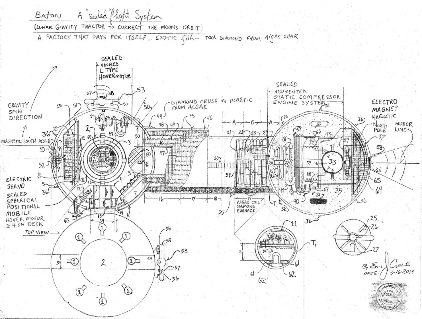
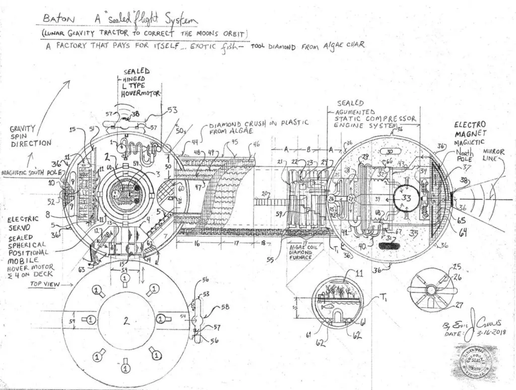
The “Baton” ( gravity tractor) is a design system intended to correct the Earth’s moon escaping it’s orbit. The moon of the Earth is a climate regulator and is critical in the life structure. The design is a sealed flight system implementing electric propulsion able to break Earth’s gravity on a fuel less generator system.
The design is not excessive in cost and repays the initial construction cost as it is also a factory producing rare fish, plant life and diamond as a function of it’s construction. This allows for the gem and products to be brought to the ground to then counteract the cost involved with the craft’s construction..
The design intended to then also be able to mine asteroids to then repay the Federal debt incurred by the United States of America also to act as a high speed comet / asteroid interception tool to then mitigate stellar object impact…it has the travel speed required unlike other design systems…The total system using a spider web style net with multiple Batons for asteroid or comet mitigation.
Note – the landing gear for vertical decent then upon the right sphere as depicted and will follow the contour to the sphere ( hinged at 180 degree quadrant point (as depicted) with the arches the slightly past the 90 degree quadrant point and the 270 degree quadrant point the from bow the 180 quadrant point then a center point with a polar
array ( @22.5 degrees forming a rib shape basket shape), with landing extension arch ski’s powered by hydraulic pistons and electric hydraulic pumping system able to the retract to form a multiple position landing system to allow for the total baton to tilt to then come to rest upon the left side landing gear.
In high velocity flight “particle gain” due to permeation…and ” electrical charge gain” from high velocity space travel must be observed as it is a factor in the safe operation of the engine designs! The bow then having frozen water ice when in high speed flight as a safety barrier..
* Note – the “L” type hover motor then depicted above the egress air lock is the operational system to “extend -the air lock .. the motors are then able to rotate within the “walls ” of the air lock frame to open and close the system ( the air lock “L” system the upon the frame operated in tandem with a pneumatic air lock opening piston system that also has an oil pressurized ( by air pressure ) final compression lock ( hydraulic pneumatic with air pressure sensors to ensure the air lock is “closed correctly” intact seal safety sensor system. Carriage able to eject with “L” type Wall motors after redundant manual lock system is free.
Parts List
1. “L-Type” hinged mounting hover motor (used for atmospheric escape )
2. Spherical positional mobile ( sealed force vectoring) sum of four hover motors mounted upon both sides of the center flight desk that has 360 degree rotational capacity within itself via flight deck rotor motor
3. center flight deck
4. “air lock” entry hatch (pressure sealed)
5. “air lock” entry access ramp hand rail s with ladder rung each side
6. retractable stair case ( pressure seals redundant pressure sensor system for chamber)
7. cargo space also contains HVAC and CO2 scrubbing system(redundant ) ie.. two independent system
8. Hydroponics
9. water storage tanks
10. Hydroponics water pumps
11. bee hives / plant lamps
12. craft landing gear ( retractable),
13. landing gear “manual” hand crank ( with reduction gearing to make the weight seem less)
14. stair case “hinge”
15. anchor “hoop”
16. craft “utility “tool bay” ( contains repair tooling and parts production “printers parts production / and smelters”
17. Helm with flip deck ( rotates the position for atmospheric lift vs. hyper speed flight ) inner circumference
sum of two spiral stair case ( zero and 180 degrees), with impact resistant riser under the hand rails wall
(carbon graphite)
18. Quarters / galley / lavatory
19. Algae coil with multiple Aquaponics for fish production
20. ladder hand rails with walk “hall” ( while in gravity spin )
21. Algae coil maintenance port (cap allows for Ph testing also contains the couplings for water feed, CO2 feed,
and plant food feed.
22. Algae coil flow valve control / water circulation pump – algae coil vent valve ( directs the algae to the
processing chamber to oil extraction fuel production and or plastic hydrocarbon stratification for plastics
production to produce outer hull plastic “crush” to embed the diamond upon the outer hull of the vessel to
reduce the effect of high radiation
23. Algae coil redundant Sealed generator systems bank of four ( also provides electricity for the
diamond furnace / diamond press ( hydraulics / and heat system )
24. diamond furnace / high pressure press – redundant encasement high impact strength to reduce
hazard of component failure
25. Negative pressure producing electric compound jet ( causes vacuum level in number 26).
26. Vacuum sphere ( negative pressure sphere )
27. primary Vacuum sphere ( negative pressure sphere )
28. plasma return ( thermal control system outer circumference – “cold” plasma ) electric compound Vacuum
producing electric “jet engine system
29. particle accelerator return cycle ( electro -magnetic accelerator)
30. sealed force vectoring hover motor forward vector sum of eight about 360 degrees listed at
Hover Motor ( mounted upon a rotator to aid in gravity escape),
31. retro vector sealed hover motor sum of eight about 360 degrees, listed
at Hover Motor
32. inner circumference “return ” plasma coil “tube” with perpendicular return to counter act
the “static return” for the “working” pressure
33. cold plasma “sphere ( pressure rated ) plasma contains high charge… insulated redundant also with
static electricity safety system (sensors and warning system redundant ).
34. “gravity spin center point sealed force force vectoring pivot also forward flight directional stabilizer system
rotates upon electric motor core redundant ( bearing “brush” / roller ball brush system) Sum of two
independent system opposed vector discharge to cause the “center point for gravitational spin..
35. carbon graphite “mix” flotation – water displacement “foam” and contains radiation reduction fill..
36. hull cameras / sensor array spherical system to encompass all radian radar sonar motion detection thermal infra red ultraviolet geiger counter ( radiation detection), altimeter, temperature and barometric pressure sensors… etc…
37. electromagnet – also acts as an electric inductance “cage ” to channel the electrical ” charge of empty space” when in high velocity flight
38. resonance transmitter to cause a transmitter “plow” acoustics wave in electromagnetism to assist in micro
particle void space at high velocity( shape of compressive transmitter “plow” critical to “compress the
electrical charge of “empty space…” focusing critical….shape of result at rate of velocity… density
electrical of transmitter plow wave…
39. Static compressors sum of two total
40. thermal management particle accelerator “return” flow system
41. electric compound Vacuum producing electric “jet engine system plasma return ( thermal control system
outer circumference – “cold” plasma )
42. electron absorption chamber causes low pressure effect then collecting the electrons by magnetic field assisting
the channeling the “charge” in the plasma into an electrical conductor yielding a low pressure effect to allow the
total system to cause high “pressure” to low” pressure to then yield directional vectoring at high feed
replacement ie… the transmitters push at close to light speed scattering the arc system within the static
compressor then the electrical “conductor causes low pressure in the aft of the engine system to then also
recycle the electricity….
43. impact wall weighted to balance the center of weight
44. diamond “crush” embedded in the produced plastic to the outer “hull – total surface leaving the “plow and
the cameras un-obstructed as well as leaving the air locks able to open, and the docking clamps able to operate
for the remote “miner / separator escape craft, number 53, to then operate.
45. outer hull
46. locking fill pipe plastic to then fill with radiation deflection / shielding material
47. expansion gel under pressure to cause a self sealing hull
48. inter – locking metal rings with honeycomb inner force deflection grid – carbon graphite ( acts also as insulation)
49. locking fill pipe plastic to then fill with radiation deflection / shielding material
50. “hull stack” total system
51. garden supply storage space… seed storage / plant food storage slide drawer
52. communications transmitter instrumentation
53. miner “separator” ,escape craft ( may also travel in from of the Baton as a solid un-maned plow to then
deflect any micro debris
54. air lock ( sum of two / one side to then allow for entry into the separator contains
independent H.V.A.C. (heating / ventilation/ Air conditioning system also with and Amine Co2 scrubber – manual hydraulic opening and closing system – main operation by electric hydraulic hydraulic servo pumping system.
55. water tanks for Aquaponics ( tanks mount couplings for water flow and pressure hatch water tight)
56. miner separator dock locking clamps
57. electromagnetic docking guide system also a security lock out as a safety measure / the magnets must be
turned off before the hard clamp will release and required redundant combination to unlock
58. miner transmitter / remote communications
59. air compressor the 360 degree mobile casing can allow one directional intake air to the refill the
internal motors pressure as required to operate.
60. fuel less generator “power bay” / for the “tool bay / helm / Quarters, also contains septic processing used
when in gravity spin – Utility systems – system electronic management core / water recycling /
atmospheric monitoring system /
61. Aquaponics pumping / filtration
62. Aquaponics extraction long filter used for all tanks contains shut – off valves and water tight sealed
gasket encasement (reusable)… waste used in other system …. plant food.. after proper conditioning
63. landing gear ( sum of two total upon each side of the “sphere” for stability swivel foot
64. ice plow “water tank contains evaporator within the ice tank to also act as a particle trap for high speed flight
65. refrigeration evaporator
66. water pumps for filling the water ice plow tank with flow pipes
67. refrigeration control units sum of three redundant flow pipe connections
68. refrigeration system condenser also used to “heat the engine chamber able to, via air duct, heat
additional chambers within the craft as reserve / back up” heating system.
*Note – flight system must be able to “fly by wire” no electronics for emergency condition ( e.m.p. electromagnetic pulse in space might damage electronics so a manual / pneumatic assist flight control system will also be required including the 360 degree spherical positional mobile…. then engines themselves are also encased in an inductance prevention “cage” to differ an e.m.p. electromagnetic pulse ).
* Note – high energy capacity requires static electricity dissipation system redundant.. Zero unwanted inductance required. magnetic filed insulation encasement also electrically non conductive encasement ( electrical insulator for all components then rated at the thermal operational rating.
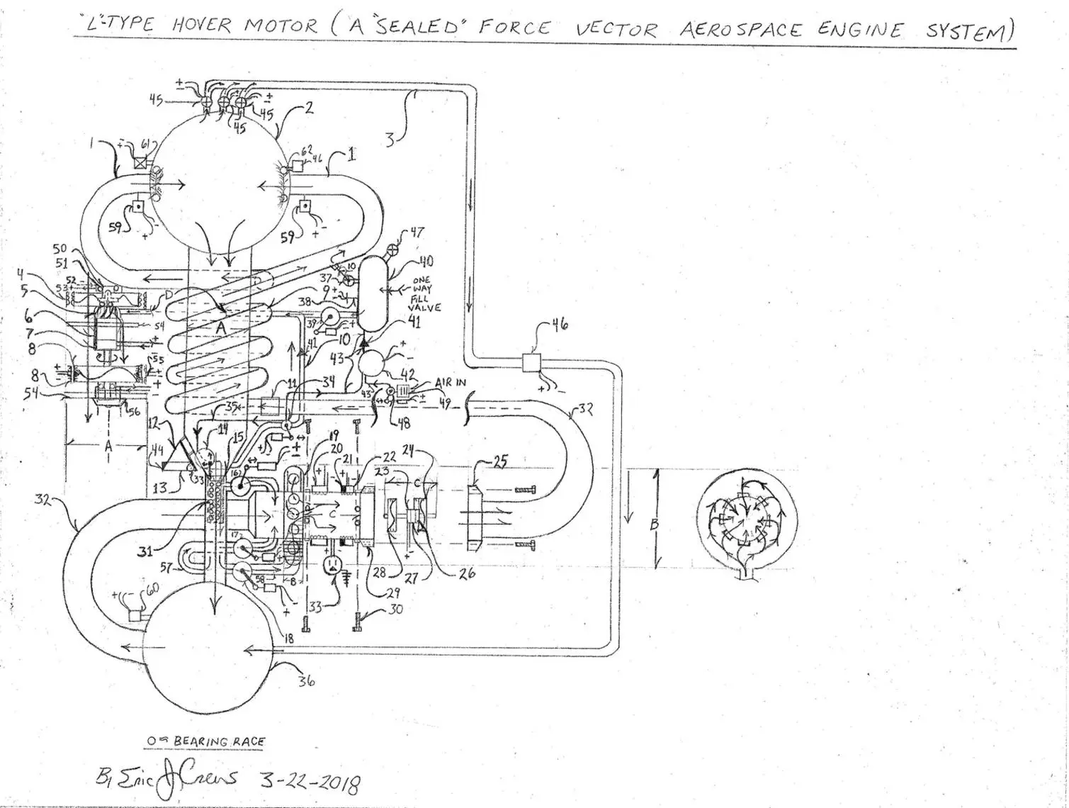
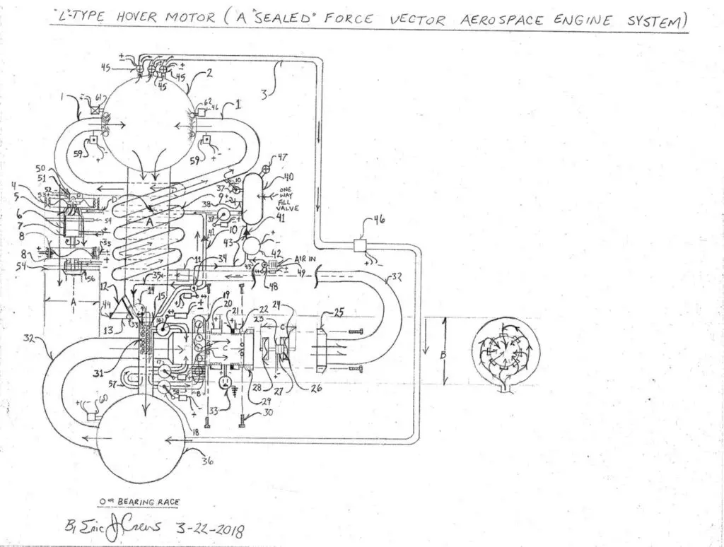
“L – Type” (sealed force vectoring pneumatic hover motor) also as fixed motors number 30 and number 31 in the retro position number upon the top drafting of the “Baton”
* Note the system surrounding the flight mobile have the capacity to “hinge power assisted to then upright the vehicle for vertical flight when in the “landed” position.
Note – high energy capacity requires static electricity dissipation system redundant.. Zero unwanted inductance required. magnetic filed insulation encasement also electrically non conductive encasement ( electrical insulator for all components then rated at the thermal operational rating.
Parts List
1. pneumatic return tube ( “static” in the force equation “of the return force air flow” in the “top” of the engine
system then perpendicular injection post return coil “Tube”
2. “top” high pressure sphere
3. max pressure pressure relief tube ( a safety system to the maximum pressure in the top pressure sphere
4. transonic impeller generator
5. pneumatic impeller
6. ratio gear set ( by the pneumatic impeller, number 7 with the ratio within the gear set at 1:10 rotations
7. electric motor
8. dual electric motor with hall effect R.P.M. sensor transonic propeller / compressor – drafts number 4 by
suction compounds rotation
9. pneumatic “return tube”
10. high pressure pneumatic flow tube
11. flow tube coupling
12. electronics bay / avionics
13. counter weight centers/ balances total system vertical center line
14. aft thrust focus gate “positioner” (gate position driven pneumatically – natural position closed via coil retention
and expansion springs)
15. aft thrust valve “thrust gate”
16. baffle valve operated by solenoid
17. lower vacuum valve operated by solenoid
18. lower vacuum valve operated by solenoid
19. 360 degree orifice intake manifold
20. field coil / Stator generator
21. magneto field coil
22. field coil / electric motor
23. electric motor with internal 1:20 ratio gear set – high ratio side tandem rotating to number 24
24. transonic armature ” propeller core pneumatic compressor”
25. electric compressor assembly housing
26. commutator
27. thru bore electricity transference ” slip ring”
28. electric “pneumatic draft compressor generator”
29. thread bore
30. bolt
31. thrust casing internal baffle
32. vacuum tube
33. receptacle – connects number 33 to number 33
34. main compressor jet pneumatic assembly adjustment valve allows pneumatic air flow to the main
assembly pneumatic impeller
35. pneumatic flow tube – air pressure from within the valve , number 34 to then operate the
aft “exhaust valve – gate valve”
36. vacuum sphere
37. max pressure safety valve vent into the upper pressure chamber via tube
38. temperature and pressure sensor sensor
39. pneumatic “Start ” valve operated by pull cable and solenoid actuating level
40. pneumatic pressure tank
41. pneumatic one way flow valve
42. electric air compressor
43. high pressure pneumatic flow tube
44. infrared / communications / radio systems sensor receiver transmitter electronics
45. pneumatic pressure sphere max pressure safety valve vents via tube to the negative pressure
vacuum sphere , number 36
46. plasma arc static electricity dissipation box with pipe coupling reports to logic processing system
governing electronics
47. pneumatic pressure max pressure ” safety valve” exterior system venting to the interior of the space craft
48. air compressor intake flow valve actuated via solenoid / or manual positioning via cable
49. air compressor intake air filter and air filter box
50. commutator
51. roller ball “brush system
52. electricity generator “return (negative) wire
53. electricity generator “Hot” (positive) wire
54. main electric jet bracket support system “mounts” the electric jet assembly
55. redundant sum of two R.P.M. ( revolutions per minute) hall effect sensors
56. jet end cap bearing cap assembly (both terminal ends of the electric jet)
57. vacuum flow tube / suction tube
58. vacuum flow tube / suction tube
59. top pneumatic pressure sphere P.S.I. ( pounds per square inch ) pressure sensor
60. vacuum level sensor ( sum of two independent circuits two sensors in one unit)
61. air flow capacitance sensor – detects electrical charge building within the air flow and compensates for
the static electricity via actuating number 62
62. static electricity dissipation “halo” connected to number 42 plasma arc box.
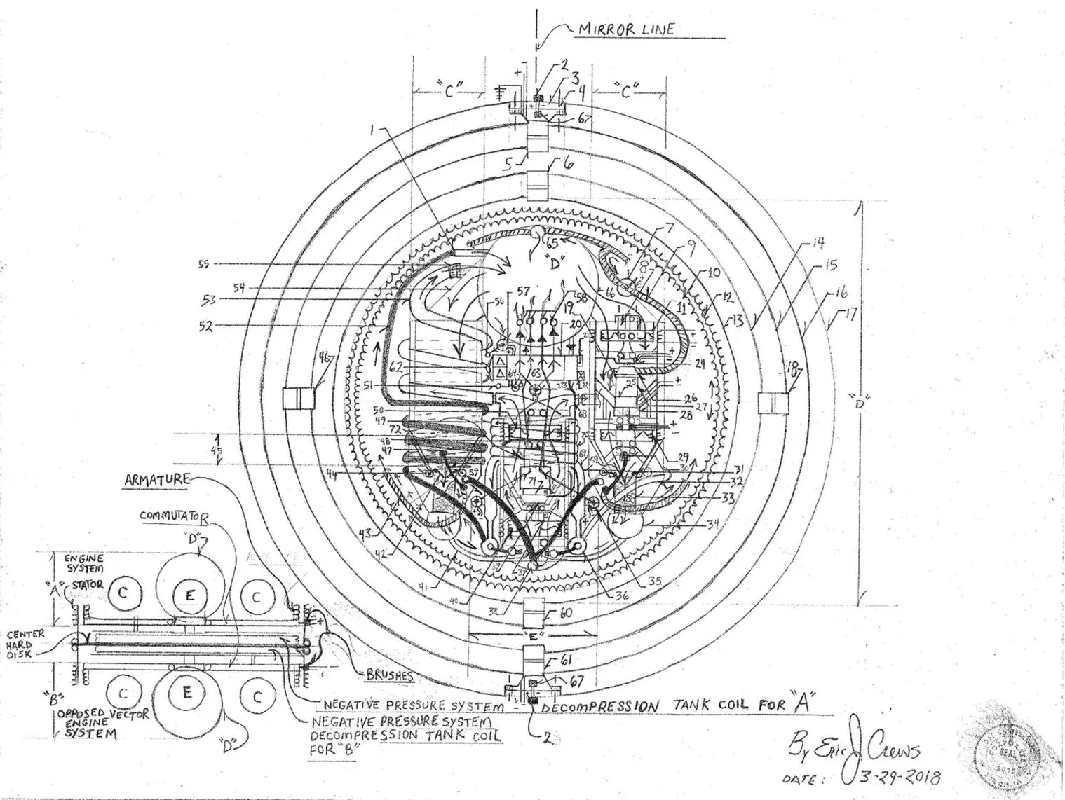
Augmented Static Compressor
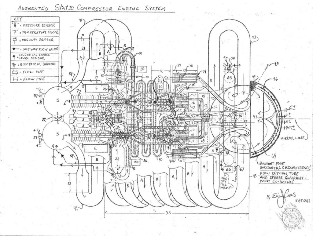
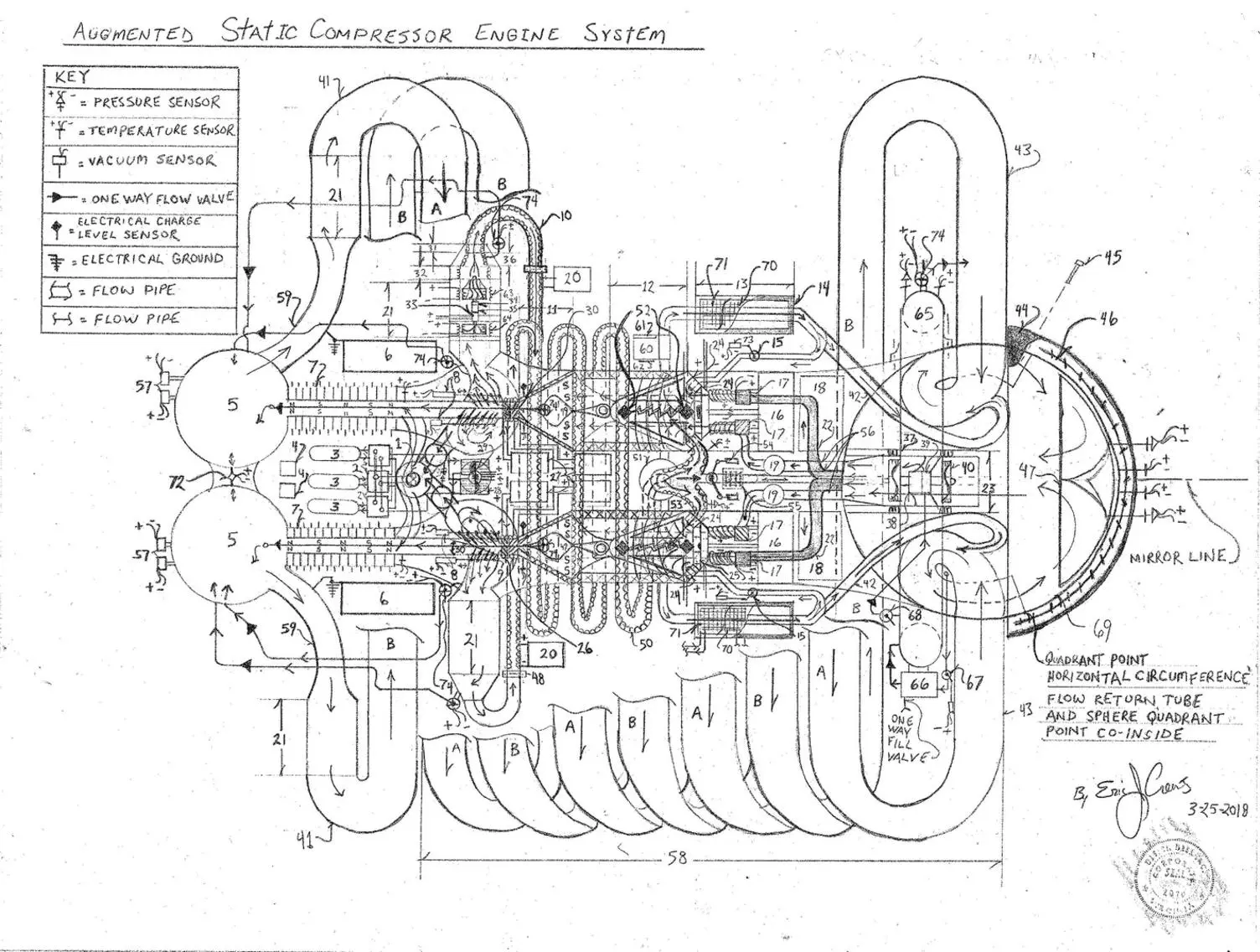
* Note – multiple selection of path way the engine system the “running” with cold plasma causing ionized inert Noble gas then as an option or the design my “run” vacuum void then revealing the rate of “replacement” by using the transmitter to carry / compress radical electron in the magnetic bottle force vectoring toward the “compression venturi and moving to the low pressure absorption “effect via the electromagnetic electron absorption system in the aft of the engine system… ie the design can “run as a vacuum with hyper excited “free electron then being compressed by the emanation wave from the micro wave transmitter system…
Within the frequency chamber a “resonance” problem might occur so an “off set” in the wave pattern pulse not to cause embrittlement due to vibration ( random pulse “transmitter” and modulation intensity not to cause resonance).
Note – high energy capacity requires static electricity dissipation system redundant.. Zero unwanted inductance required. magnetic filed insulation encasement also electrically non conductive encasement ( electrical insulator for all components then rated at the thermal operational rating.
Parts List
1. refrigeration evaporator (cooling cylinder)
2. refrigeration systems / contains refrigeration switch valves and redundant refrigerant compressors
3. refrigerant pressure vessel (nitrogen)
4. plasma static electricity arc dissipation system “plasma box” controls static electricity by arc dissipation
and inductance of plasma charge to a transformer to then channel the static electricity for use.. recycle
5. vacuum sphere
6. fuel less generator bay ( hydraulic draft accelerators ) systems control electronics sensor multi
wire “bus” connector receptacle
7. magnetic electron absorption system (causes collection of the flow electrons and channels the current
for reuse within the system
8. flow gate solenoid ( allows the plasma to vent at variable levels)
9. louver valve
10. particle accelerator
11. magnetic focus venturi (funnel)
12. diamond arc chamber contains circular main microwave transmitter and “ring transmitters surounding
the electron emitter ( outer casing is a “magnetic bottle”)
13. refrigeration “chamber” cools the return plasma flow system
14. refrigeration chamber insulation
15. ring transmitter core orifice inlet control valve
16. transmitter electronics for “main transmitter ring and the four “ring transmitters”
17. electron emitter injector electronics
18. slide drawer fuel less power system fuel less generator “bay”
19. plasma flow meter ( measures rate of velocity )
20. particle accelerator electronics( sum of two independent system in flow system
21. draft generator electric – pneumatically / driven ( by draft velocity) compression jet speed up on
it’s own displacement while generating greater electricity levels / current levels governed in number 6
same parts format as number 23
22. main plasma flow tubes
23. plasma accelerator compounder / with pneumatic start impeller also generates electricity and
motors by the high speed output rotation of the electric jet
24. ring transmitter ( microwave transmitter )
25. Main transmitter circular ring allows electron emitters , number 17, to discharge within the
radius with an open passage to the magnetic venturi ( micro wave transmitter center with
diamond “arc connector” receptacle )
26. magnetic venturi exhaust focus electromagnets ( may be elongated in length to also for more active thrust length)
27. magnetic venturi exhaust focus electromagnets control electronics with inductance shield “cage” to prevent
E.M.P. ( electromagnetic pulse) from effecting the electronics
28. refrigeration condenser
29. dual electric motor ( roller ball “brushes” ) blower fan / may accept air flow duct work to channel the
hot air to chambers
30. magnetic venturi “gate valve ( assist in focusing the electron flow pressure restriction valve)
31. electron focus electromagnets
32. electron focus electromagnets
33. roller ball “brush” electric motor dual output shaft
34. R.P.M. sensor
35. 1:10 ratio gear set connected to the input rotation , number 64 tandem and tandem on the output side
to electricity generating transonic number 63 also with roller ball “brushes”
36. magnetic focus venturi “funnel”
37. electric motor transonic impeller core circumference roller ball electricity transference
38. 1:20 ratio gear set output rotation tandem with pneumatic start impeller number 39
39. pneumatic start impeller
40. P.M. (permanent magnetic ) generator compressor / transonic propeller – armature is the field coil magnetic
the outer casing then wired to step voltage
41. flow “U” pipe
42. cold plasma return
43. perpendicular return flow tube ( both “A” and “B” coil tubes)
44. insulated plasma sphere pressure casing
45. insulated casing bolt array center point is the mirror line
46. refrigeration evaporator
47. plasma flow guide and Neutrino detector / particle gain detector….
48. bolt plate pipe union
49. magnetic venturi insert / guider the plasma flow
50. particle accelerator
51. plasma flow distributor
52. diamond arc nodes one side positive one side negative electrical polarities
53. plasma manifold / distributor internal guide electro-magnetics
54. flow gate valve solenoids sum of two upon the gate valve on the flow tube also with manual actuation
via lever and cable
55. flow pipe evaporator refrigeration cooling system
56. flow tube assembly ( sum of four out / into the electron “ring transmitters” and one center position bi directional tube flow
57. vacuum level sensors
58. spiral coil flow return tubes both “A” and “B” coil flow tubes
59. plasma flow tube
60. electronics mapping system control circuits instrumentation gauge port for multi wire bus for remote
instrumentation critical function by low tech mechanical control systems
61. instrumentation display panel
62. multi wire “bus” connector to systems valve solenoids and systems sensors / motors and generators
63. electric motor compressor core roller ball “brushes” armature outer circumference is the commutator
64. generator plasma impeller “flow draft effect” then accelerated total system
65. inert gas ( noble gas ) pressure toroid ( doughnut shape pressure storage tank)
66. inert noble gas reclamation gas compressor ( prepares for the subsequent re- Start by lowering the pressure
in the system storing the inert gas under pressure within the toroid pressure storage tank
67. inert gas compressor intake actuation valve actuated by level and or the automatic solenoid system with fail
safe redundant safety check
68. “start” flow valve ( causing the generation of electricity to be applied to the internal system
acceleration…post regulation for electricity levels
70. external cooling exchanger ( outer space cooling exchanger ) cools the plasma flow by the ambient
temperature of outer space via fluid medium then pumped via electric hydraulic pump
71. refrigeration evaporator
72. vacuum balance valve with powered valve and safety function to maintain vacuum
73. solenoid valve position control
74. max pressure safety valve vents via tube to lower pressure contains actuation sensor to indicate
actuation “level to adjust total system to bring it back into it’s operating parameters a safety valve
Flight Mobile ( Spherical positional system) the rings rotate upon the servos for flight vector course correction…
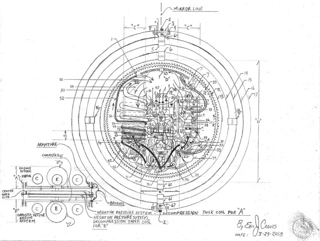
Note – high energy capacity requires static electricity dissipation system redundant.. Zero unwanted inductance required. magnetic filed insulation encasement also electrically non conductive encasement ( electrical insulator for all components then rated at the thermal operational rating.
Parts List
1. pneumatic flow tube pressure coupling
2. infra red transmitter / receiver
3. stationary mounting plate
4. bore hole mounting system
5. electric servo motors / redundant electric motors ball bearing “brushes” / sealed lubrication
contains thru bore electricity transference slip ring
6. electric servo motors / redundant electric motors ball bearing “brushes” / sealed lubrication contains thru
bore electricity transference slip ring
7. electric actuation / “acceleration / pneumatic flow valve
8. commutator
9. flex flow hose pressure rated
10. flight deck armature
11. electricity generator with magneto transonic “pneumatic draft accelerator”
12. field coil flight deck electric motor
13. hard center flight deck “disk”
14. mobile system flight “ring”
15. mobile system flight “ring”
16. mobile system flight “ring”
17. mobile system flight “ring”
18. electric servo motors / redundant electric motors ball bearing “brushes” / sealed lubrication contains thru
bore electricity transference slip ring
19. 1:10 ratio gear set high side rotation tandem to number 26
20. generator “bay” fuel less electricity generator systems – redundant also contains exterior input air
compressor to re-pressurize the engine system
21. Main pneumatic start valve (actuated by remote infrared /radio transmitter )
22. plasma arc “box” static electricity dissipation system redundant system with actuation indication as a safety
feature with interrupt and fault signal then relayed to the ships helm
23. vacuum system main manifold main safety pressure safety valve actuates and reports level of
actuation govern the systems operating parameter to keep the vacuum system within it’s mechanical tolerance
24. R.P.M. ( revolutions per minute ) sensor
25. electric motor
26. pneumatic counter tilt impeller / also aids in total speed incline
27. electric motor counter tilt
28. shock casing electrical ground point and 1:20 ratio gear set high side rotation tandem to number 26
29. electric motor transonic “pneumatic impeller redundant sum of two electric motors / ball
bearing “brushes atop circumference commutator
30. thruster venturi max pressure safety valve vents to the vacuum system
31. vacuum system pressure manifold
32. pressure flow pipe
33. thrust baffle
34. vacuum sphere
35. max pressure over pressure safety valve
36. distributor pressure sphere
37. vacuum accelerator commutator
38. negative pressure intake
39. vacuum accelerator “start pneumatic impeller
40. transonic electric motor (draft accelerator)
41. vacuum flow tube
42. thrust venturi “flow restriction valve (causes high displacement force via flow restriction) pneumatic
and electric motor actuation
43. travel coil pneumatic circular “static force” counter act technique( volume of the interior of the travel coil the
circle / circumference of the flight deck disk, to then have the volume and pressure re-tainment for
total decompression the blow down cycle
44. venturi thrust gate restriction gate control actuator electric motor and pneumatic servo/ impeller actuation
45. thruster venturi / funnel
46. electric servo motors / redundant electric motors ball bearing “brushes” / sealed lubrication contains thru
bore electricity transference slip ring
47. thrust chamber max pressure over pressure safety valve with actuation sensor to also report to the
system governing electronics to keep the speed and pressure within it’s mechanical operating parameter
48. generator high speed transonic compressor (vacuum producer drafts number 40 into acceleration
49. vacuum accelerator force static primary discharge port pneumatic pressure flow coupling
50. vacuum draft compressor
51. flight deck circumference travel coil coupling ( to air compressor)
52. pneumatic flow pipe
53. “static force” / perpendicular flow return main flow manifold “coil flow tube”
54. thruster intake manifold
55. pressure coupling
56. main pneumatic pressure sphere over pressure safety valve vents to travel coil
57. main pneumatic pressure sphere over pressure safety valve with actuation sensor adjust system parameters
speed current levels and directs flow to the “travel coil” then also de-compressing the system in the main
pneumatic pressure sphere.
58. main pressure sphere return ports
59. thrust chamber max pressure by-pass flow pipe contains max pressure valve upon venturi casing (a one way valve)
60. electric servo motors / redundant electric motors ball bearing “brushes” / sealed lubrication contains thru
bore electricity transference slip ring
61. electric servo motors / redundant electric motors ball bearing “brushes” / sealed lubrication contains thru
bore electricity transference slip ring (upon all mobile rings)
62. static electricity dissipation system ( plasma arc box/ with reduction transformer to “drain” the plasma of
electricity to the make the harvested electricity reusable
63. fuel less generator “bay ” and mapping control electronics ( contain redundant air compressors to dump
the travel coils and re-fill the main pressure sphere
64. electric valve dumps “travel coil” and re-fills the main pressure sphere
65. travel coil “active flow ” one way valve pressure return coupling and port
66. main pressure sphere
67. internal receiver / transmitter
68. pneumatic “start flow tube connects the start valve to the pneumatic impeller, number 39 ( start valve connects to
the main pressure pressure sphere.
69. pressure manifold ( vacuum accelerator)
70. vacuum accelerator pressure coil ( tube manifold)
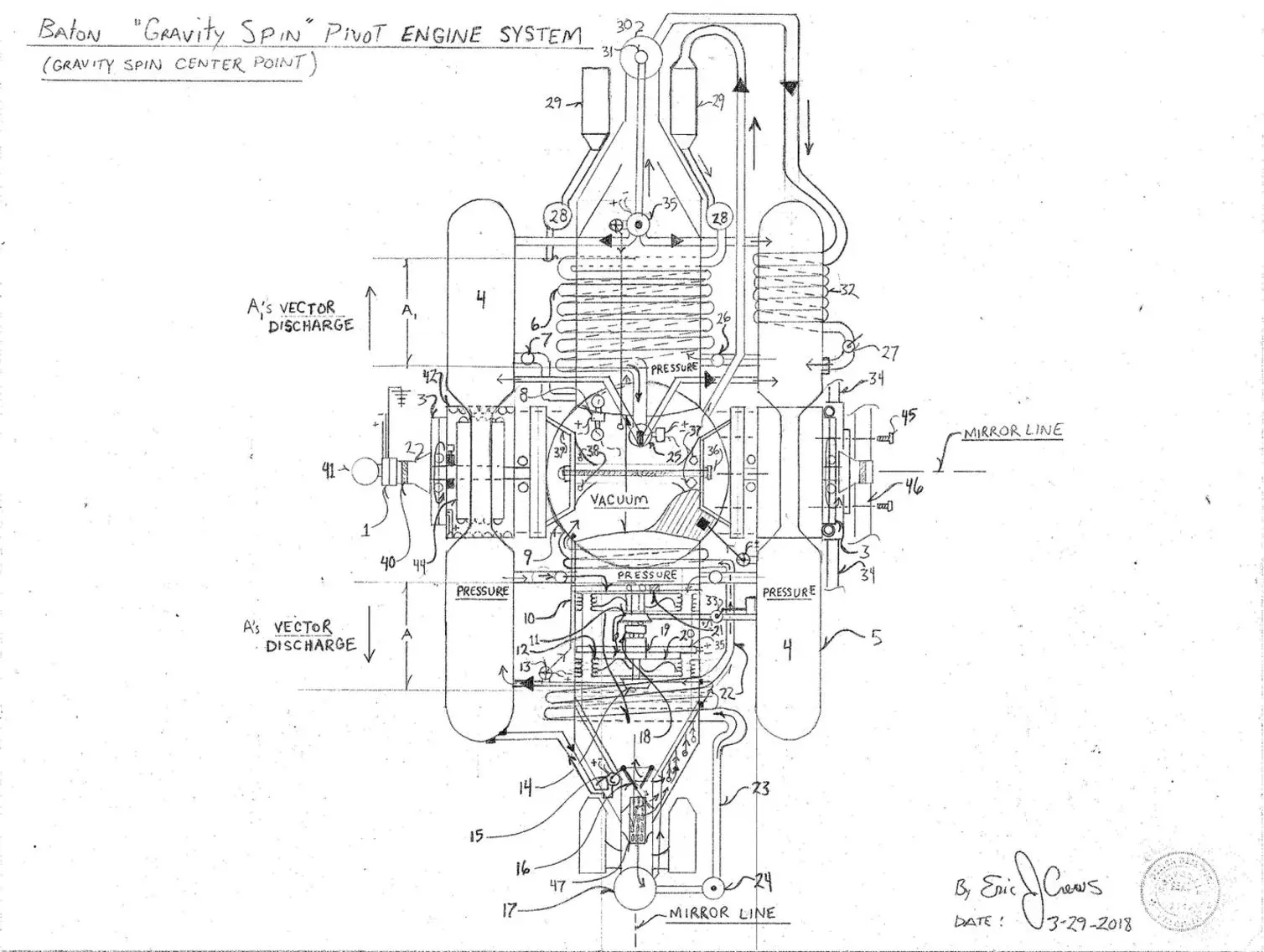
Gravity Spin Pivot Engine System
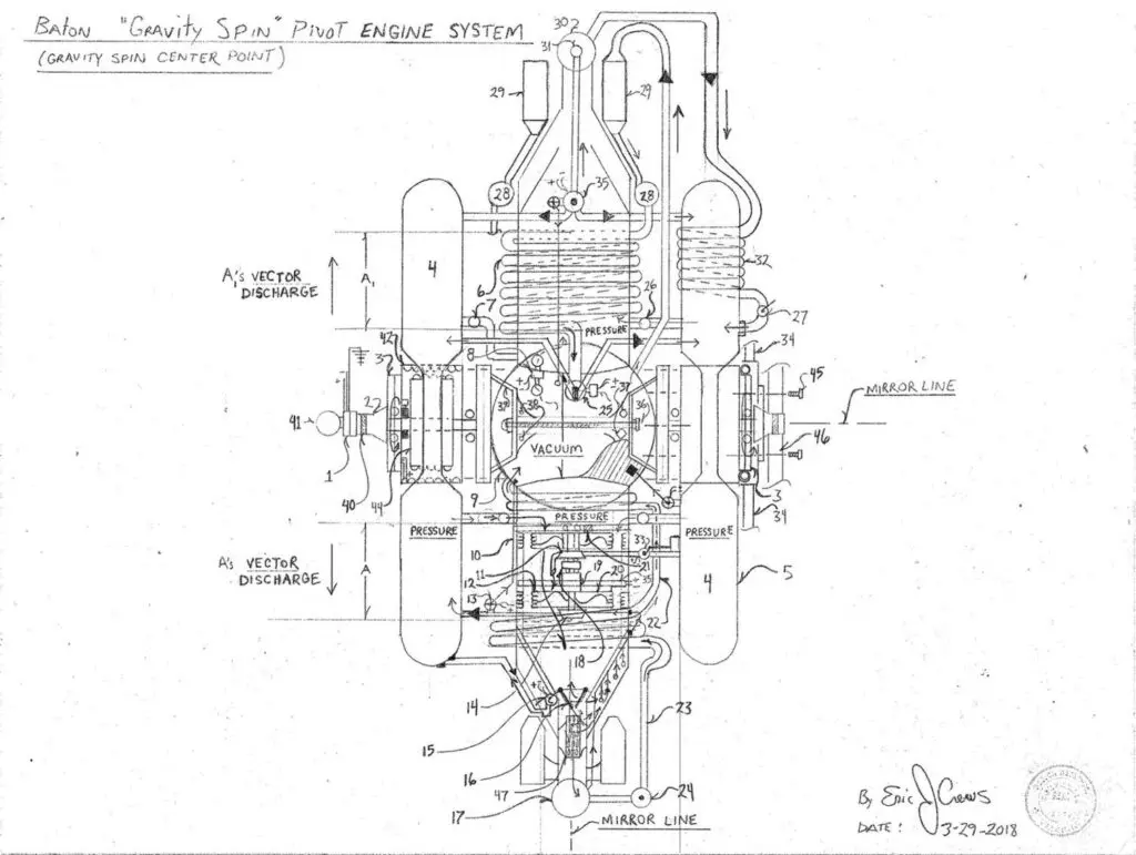
* note “A” is the same as “A1 ” but force vectored in the opposite direction…
The placement of component the mirror line then is reflecting the same components left as right upon the opposed sides of the mirror line as well as the mirror line mid….. Number 29 is the same as letter “A” with all connecting flow and power systems the same discharging to the tapered end.
Note – high energy capacity requires static electricity dissipation system redundant.. Zero unwanted inductance required. magnetic filed insulation encasement also electrically non conductive encasement ( electrical insulator for all components then rated at the thermal operational rating.
Parts List
1. Thru bore electricity transference slip ring
2. mount assembly
3. thru bore electricity transference slip ring also contain communications and logic control circuits
multi wire “bus” clip port on the stationary outer 1/2 of the slip ring
4. pneumatic pressure tanks
5. static electricity grounding point mounts and plasma arc box dissipating static electricity
6. return force static counter measure “coil return tube feeds pressure to number 25 a pressure coupling with
two outlet then directed to the two pressure chambers ,number 4
7. electric actuated pneumatic pressure feed valve feeds the system pressure only when excessive vacuum is
produced thru number 8 effecting the core vacuum chamber to greatly / prevents vacuum
chamber , number 9’s collapse
8. vacuum switch… allows vacuum thruster “A1” to pull ultra low pressure within the vacuum chamber
9. vacuum sphere
10. electric motor transonic compressor
11. pneumatic “Start” impeller also acts as a speed incline impeller
12. pneumatic transonic impeller and generator contains magneto to excite the generators field coil / voltage regulated
13. flow line / tube max pressure safety valve sensor reports actuation and dumps pressure via tube to the
vacuum chamber to compensate for too high a pressure within the pressure storage tanks number 4
14. centrifugal pneumatic compressor “air pump” to then re pressurize the pressure storage tank, number 4
15. thrust venturi gate electric motor actuation also pneumatic actuation restricts venturi flow to increase
pressure discharge
16. venturi restriction valve focuses displacement force
17. vacuum sphere ( negative pressure sphere)
18. R.P.M. sensor
19. electric motor
20. transonic impeller accelerates total system by velocity of flow
21. breaking disk caliper system / hydraulic
22. pneumatic flow tube
23. pneumatic flow tube
24. vacuum level indicator sensor reports to mapping electronics / control circuit governs systems parameters
25. pressure flow distributor
26. pressure feed valve / electric and manual actuation allows pressure from the pressure tank , number 4 to
then fill the vacuum producing thruster
27. pressure retainer valve opens under high pressure acts as one war valve / natural position closed
by coil spring assembly
28. displacement flow rate meter / electric reports to mapping system control electronics
29. hyper jet electric compound jet / draft accelerator speeds up upon suction with a generating impeller and a
dual electric motor compressor at it’s intake, contains R.P.M. sensor to then assist in speed regulation
then via electronics regulation circuits
30. pressure sphere
31. pressure sphere over pressure max pressure safety valve vents pressure to the pressure tanks , number 4
32. force “static” off set counter measure a coiled perpendicular tube coil
33. pneumatic “Start” valve manual and electric actuation
34. mounting assembly tri-pod with locking bearing caps allows for 360 degree spin
35. pressure distribution valve with over pressure safety valve with sensor safety valve dumps via tube to the
vacuum chamber
36. vacuum / pressure sphere mount bracket assembly lock bolts sum of 8 about 360 degrees
37. vacuum / pressure sphere mount bracket assembly lock bolts bolts to the bracket upon the sphere
itself locking the bracket
38. thread bore upon vacuum / pressure sphere sum of 8 total
39. contour accepting bracket with gel interface to cause soft dock under compression of the mounting brackets
40. install clamp track ( a servo boom with locking clasp grabs section at the point of illustration for installation
along with the “ball end cap sphere number 41, then secured while tri-pod installation is being done .
41. installation “ball” over head boom gantry crane then clamps both ends for installation also with the robotic
servo arms then clamp locking to number 40
42. field coil stator
43. total system is 34 on main “baton” top drafting……
44. armature allows the total assembly to rotate 360 degrees
45. bolt
46. tri-pod
47. thrust baffle
* Note – It is imperative that the system final casing be free to static electrical charge formed from velocity
of the working “flow of pressure” ! Redundancy in the control of the static electricity for final systems casing
is a good idea…
* Note- the gravity spin system listed directly above then as two total opposed systems to produce a center pivot
for the craft to then rotate upon as a center pivot. So that the the design is twice upon the total ship
design but total force vectoring in opposite directions. The spherical position mobile then also used in
tandem with the pivot system to stable rate of rotation an integrity of circumference as the spherical
positional mobile will adjust the spin to stabilize the rotation as required…