Drum Generator
The “Drum Generator” is a buoyancy displacement generator system that also implements “hydraulic draft” of a “pressurized fluid”. The system uses non electrically conductive, non flammable, hydraulic fluid as the working medium.
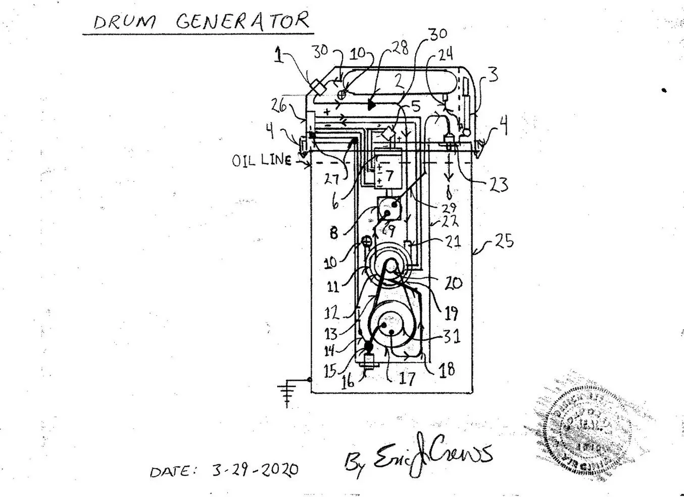
Parts List
1. pneumatic ( air pressure) valve system ( start sequence “valve” / used in tandem with oil valve actuation number 15)
2. pneumatic pressure storage pressure tank
3. manual hand air compression air pump ( fills the pneumatic pressure storage tank via air hose connected by compression couplings
to the air pressure pressure tank
4. drum (55 gallon oil drum ) cap compression clamps – sum of 8 about 360 degrees from the top view center point
5. voltage regulator
6. magneto (permanent magnet electricity generator )
7. main high voltage generator , 240v Ac (alternating current)
8. trans-axle (differential gear set ) tandem rotating with number 9
9. hydraulic impeller ( internal fluid by-pass channel with oil pressure sensor – the said oil pressure sensor then reports to the logic
mapping electronics in the control panel to then adjust the electricity “re-introduction level via potentiometer causing the current from
the generator, number 7 to be reduced in level when feeding current to number 11. This acts a a safety system also aiding in the “run”
rate ( run R.P.M. – run “revolutions per minute” ) electricity re-introduction level.
10. pneumatic over pressure max pressure safety valve – vents over pressure
11. electric drive motor (dual shaft)
12. hydraulic pump
13. drive belt
14. valve control arm and pull cable system – operates the valve – valve contains coil spring re tension to the valve closed position the
valve then kept open by the upper lever on the control panel with safety kick off is the system incurs “run away” effect as a safety feature
15. hydraulic fluid valve
16. hydraulic fluid inlet coupling oil filter unit
17. large pulley
18. oil flow pipe
19. pneumatic ” start” impeller (centrifugal type impeller)
20. small pulley
21. oil pressure coupling
22. internal oil displacement “drum”
23. oil return coupling
24. pneumatic pressure hose and one way flow fitting upon the pneumatic pressure tank number 2
25. 55 gallon oil drum
26. electricity control panel ( contains circuit breaker switching and electricity management to be able to reduce final electricity output
voltage – 120v Ac or 240v Ac ) electronics thermal control system. The unit contains electric cooling fans to vent heat.
27. oil flow “Start” valve valve pull cable guide pulley
28. one way valve upon the pneumatic flow pipe
29. oil flow pipe
30. pneumatic flow pipe
31. hydraulic impeller tandem rotating with the large pulley number 17
Description
The Oil drum cap then contains an internal bracket system to hold stable the components in the flow system placed to then function correctly. Exposed union shafts then held stable by sealed lubricated bearing races.
The system causes rotation by buoyancy displacement of hydraulic oil then caused to accelerate in velocity to incur high speed flow of oil with the assistance of the electric motor then energized by a percentile of generated electricity from number 7.
The tandem rotating components numbers 11 ( armature), 12 ( internal hydraulic pump wheel), 19 (pneumatic impeller), and 20 (drive pulley) will cause the preceding hydraulic impeller, number 31 to cause system rotation producing adequate rotational rate in number 8 by rotating number 9’s internal hydraulic impeller to then produce electricity in number 7. The “run” speed then regulated by final electrical production being measured (gauge / meter) adjusting the electrical re-introduction rate ie… the feed current directed back to the system electric motor number 11.
The magneto’s initial electrical output current then is voltage regulated by number 5 and electrified the Stator / field coil for the main high voltage generator number 7. Electrical output then upon the control panel that can be made to be weather encased for out door installation. The system is electrically grounded!
The design uses gas sealed ( inert noble gas) motors and electricity generators to prevent low level Ozone formation.