Sparks Engine System
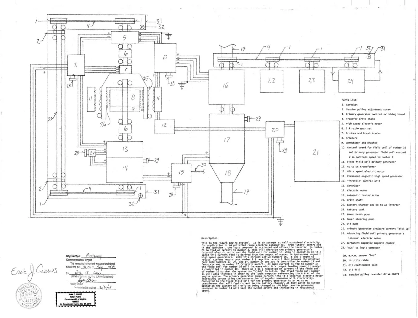
Description: This is the “Spark Engine System”. It is an attempt at self sustained electricity for application in an unlimited range electric automobile. From “Start” controlled in the ignition , the logic computer is activated and allows the inverter in number 20 to feed Ac current to number 3. This will energize the primary generator’s internal electric motor and the field coil for number 16. When in operation at idle speed this current feed is derived from the output of number 14 (permanent magnetic high speed generator). With this circuit active numbers 26, 8 and 9 begin to rotate. Current return post number 8 ( negative return ) then becomes the positive feed into numbers 13, 27, and 14. Number 14 out put is controlled in number 15 and feeds current to number 17 (electric motor). As more current is fed to number 17 the field coil for number 16 will increase with it’s output feeding power to number 5 controlled in number 10. There will be a reduction of current in the field coil of number 16 so that the system can “climb” in R.P.M. The fixed field coil number 11 will also increase in power by the logic computer referencing the R.P.M. of the engine system. The primary generator dumps current into it’s internal electric motor increasing torque using the Conservation of Angular momentum with electricity. Connected to the fixed field coil for the primary generator is an Ac to Dc transformer that will feed current to the battery charger. At that point in system operation the battery will only be being charged as the high tension generator produced in number 14 will keep the system active and increasing in rotational speed. The small circles are bearing races on the small drive shafts and primary generator armature. Brush less electrical transference can be adapted for this design with in the motors and generators so that the systems longevity is extended. As an addition to this design a 1:4 ratio gear set can be inserted between number 17 and number16. Parts List: 1. Sprocket 2. Tension pulley adjustment screw 3. Primary generator control switching board 4. Transfer drive chain 5. High speed electric motor 6. 1:4 ratio gear set 7. Brushes and brush tracks 8. Armature 9. Commutator and brushes 10. Control board for field coil of number 16 and Primary generator field coil control also controls speed in number 5 11. Fixed field coil primary generator 12. Ac to Dc transformer 13. Ultra speed electric motor 14. Permanent magnetic high speed generator 15. “Throttle” control unit 16. Generator 17. Electric motor 18. Automatic transmission 19. Drive shaft 20. Battery charger and Dc to Ac inverter 21. Battery tank 22. Power break pump 23. Power steering pump 24. Oil pump 25. Primary generator armature current “pick up” 26. Advancing field coil primary generator’s internal electric motor 27. permanent magnetic magneto control 28. “Bus” to logic computer 29. R.P.M. sensor “bus” 30. Throttle cable 31. Oil confinement case 32. Oil fill
33. Tension pulley transfer drive shaft