Jalapi
The Jalapi is an unlimited range electric vehicle that requires no electrical storage battery. The generator then is an “Active” self sustained system by drafting pressurized oil across a ratio gear set then causing acceleration of magnetic pressure with in the electric motor attached to the”Active” generator. The design is then producing electrical current to also feed a main electric motor connected to an ” Automatic ” or “Manual ” transmission that rotates wheels upon an automotive platform. The additional pneumatic counter resistance system then counteracts the resistance incline of the magnetic fields produced while generating electricity within the generator.
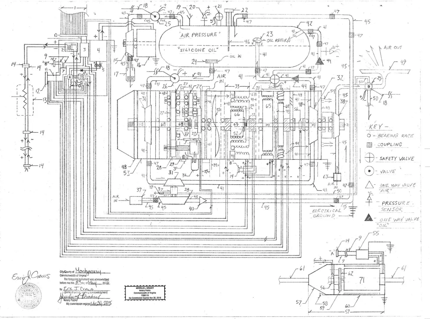
Parts List 1. Sensor wire feed “wire bus” ( wires from system components R.P.M. sensor, pressure sensors, wires for electric valve control. 2. Main power feed transformer 3. Systems logic processing unit ( system mapping circuits) 4. Dc ( direct current) to Ac ( alternating current ) electrical current inverter 5. Wire bolt post locking by nut connector 6. Voltage regulation unit with current re-introduction circuit 7. System logic circuits ( motor mapping / control circuits ) 8. Stator / field coil electricity feed transformer 9. Ribbon “Multi wire ” 10. Wire “bus” multi wire “bus” connector 11. Dash board instrument cluster plug in unit 12. “Bus” connector ( plugs in to the back of the instrument cluster upon the dashboard) 13. Main electric motor throttle unit 14. Wire “bus” connector 15. Pneumatic impeller 16. Permanent magnet dynamo 17. Air vent canister 18. Steel cord manual pull cord ( operates the valve ) 19. Pneumatic fill valve ( one way valve ) 20. Pressure sensor ( pneumatic / hydraulic silicone oil ) 21. Pneumatic max pressure safety valve prevents over pressure by venting high pressure to the exterior of the system 22. Oil fill pressure cap with dip stick 23. Oil return flow direction “cup” 24. Oil intake flow dampener ( also acts as a screen filter opens greater via high suction ) 25. Pneumatic electric and manual actuation valve 26. Hydraulic oil electric and manual actuation valve 27. Gears 28. Oil pump drive gear 29. filing catch magnet 30. oil plug threaded bolt with gasket 31. Hydraulic impeller 32.Hydraulic pump 33. Electric motor with inner electromagnetic clutch assembly 34. Blower fan / cooling fan 35. Air filter + retainer ban housing ( circumference ) air intake ports for blower fan 36. oil filter 37. 1:20 ratio gear set with high side gearing to the pneumatic compressor gear box also contains a pneumatic impeller receiving air pressure from number 50 38. Centrifugal pneumatic compressor also pneumatic impeller for the blow bar… 39. Air filter / air intake 40. Pneumatic one way valve 41. Hydraulic flow tube ( non flammable non conductive silicone oil ) 42. Combined oil and pneumatic pressure , pressure tank ( pressure rated for up to 1500 lbs. per square inch of pressure ) / safety dump set at 750 – 850 lbs. per square inch of pressure 43. Main high voltage generator and compound permanent magnet magneto assembly 44. Hydraulic one way valve 45. Pneumatic flow tube 45. Hydraulic flow tube 46. Coupling pressure rated 47. Coupling pressure rated 48. Brace bracket ( component mounting ) 49. Automotive wind shield blow bar ( assist in clean windshield when raining by blowing high velocity air across the wind shield surface )… 50. High pressure pneumatic flow tube 51. gear oil cap and fill port 52. Drive shaft end nut 53. Draft generator system casing 54. Air vent ports 55. Propeller / blower fan ( unit assembly atop number 71 the with air filter ( plus water trap and connecting mounting box water tight mounting. Also contains high tension wire mounting junctions for main electric motor feed. 56. R.P.M. ( revolutions per minute ) sensor 57. Automatic or manual automotive transmission 58. Gear position linkage / cord connector 59. Dual circular bolt plates ( split “fly wheel” ) 60. Main electric motor stator / field coil 61. Drive shaft ( to wheels ) 62. Main electric motor fly wheel 63. Air intake / air filter 64. Compound wound magneto ( wire winding allows for increased / variable magnetic pressure to be induced ) 65. High Voltage generator 66. Electromagnetic clutch ( locks by magnetism induced by electrical current ) 67. Main high voltage generator stator / field coil 68. Drive shaft 69. Drive shaft 70. Drive shaft 71. Main electric drive motor ( propels the Automobile). Note – Wire “bus” connector connects “A” to “A” and connector “B” connects to “B”. * Note – Before number 23 upon the main line “tube” oil return into the main pressure storage tank then is additionally component ” HZ” posted upon The ratio gear set “Tilt” pressure then is hydraulic oil pressurized feed from post number 32 then venting the oil into the pneumatic pressure then “low” within the combined pressure storage tank…then carry tube is then of smaller diameter than the main line “tube” oil flow tube.
* Note – Additionally to the above pictorial schematic the adding a flow tube from the max pressure safety valve , number 21, with number 21 then becoming a two stage pressure relief valve then channeling via pneumatic flow tube to the pneumatic impeller , number 38 then tandem with the main generation production assembly … to then cause a counter tilt ( cancels the ” torque resistance ” upon the high rotational rate side of the gear set ).
Then feeding by volume 50% – 90% of the pneumatic “gain” ( measured by pressure cm3) of the pneumatic pressure produced by the air compressor system driven by hydraulic flow at number 31,37,38 to number 38 within the blow bar compressor cycle… this occurs when sufficient pneumatic pressure is attained within the pneumatic pressure storage tank. the two stage pressure valve, number 21 the open first to the counter tilt flow cycle and the second stage then vents to open air… Note – Additional hot dot upon schematic / electrical output of number 65… hot + into number 2 connecting number 3’s ribbon ( high tension ) into number 7 ( high tension ) “system acceleration” circuits….. advances electric motor magnetic pressure and rotational rate of number 67 via connector “B”. Note – Additional component to system displayed a pneumatic impeller the of centrifugal type ( between number 38 and number 32 called impeller “A” ) rotating locked in tandem with the hydraulic pump number 32 …then fed pneumatic pressure post pneumatic compressor number 38 at pneumatic pressure storage tank pressure levels.. / regulated by variable valve on the tube flow line ( compressor then having been amplified in rotation by the 1:20 ratio gear set… ). Pneumatic impeller “a” then fed main line pneumatic velocity from component “Z” depicted upon with counter tilt for the internal ratio gear set then derived from number 42. * The additional feed tube ( “D ” ) will branch off the pressure tube that feeds the pressure tank to then impale the impeller “A”also then dumping it’s vent pressure to the pressure storage tank and or by positional valve placed after impeller ” A” to then allow for exterior venting. The additional flow tube also then contains a one way valve to prevent dual component pressure storage tank air pressure loss. This addition then is increasing the counter effect to resistance produced by the generator’s stator / field coil. * – The multi position valve upon another additional flow tube (“E” ) is also electric and with a manual cord to cause valve control with an additional inlet to also allow for another tube ( “C” ) then originating from the combined pressure storage tank pneumatic pressure feed ) to then act as a “start” burst of pneumatic pressure to assist in the mass of the generator assemblies then accelerated into inertia . When tube Tube “C” is then being actuated upon start up the venting of the additional impeller (“A” ) is the directed by valving and directional flow tube to the low pressure environment ie the intake feed of pressure in number into number 38 at number 39. Number 39 then being a directional gate intake valve system ( louvered intake restriction system ) to use the cycling of pressure… Description… This design starts by venting high pneumatic (“air” ) pressure through a valve then discharging across a centrifugal pneumatic impeller with the pneumatic impeller then attached to a drive shaft spinning a permanent magnetic dynamo producing Dc ( direct current ). The produced Dc current is then inverted to Ac ( alternating current ) then regulated by voltage regulator and the current then actuates number 26 and assembly 33. The electrical current then locking the electromagnetic clutch engages the rotation amplification gear set between the hydraulic impeller and the hydraulic pump. The hydraulic pump is the rotating at greater rate than the hydraulic impeller causing an advancement of rotation. The electrical current then produced within the Magneto is then also then channeled via circuit pathways to the field coil / stator of the electric motor ( assembly 67 ) and generator number 65 also increasing the electrical “pressure ” ( current level ) within the magneto number 64 then yielding more work ability by creating higher current levels. The systems gear set resistance produced from causing greater rotation using a ratio is then a resistance force then being counteracted upon by the electrical pressure fed to the electric motor number 67. The basal oil pressure then also in proportion to the air pressure atop the oil. This makes the ” air” pressure act as a “piston” then giving pressure to the oils discharge. The oil flow then between the oil impeller and oil pump upon drive shaft number 70 then also contains between a oil impeller that is the rotating a “counter tilt” ratio gear set then also attached to a pneumatic centrifugal compressor causing an increase of system pneumatic pressure… ie. ” pneumatic pressure gain”. This allows for rate of system speed to increase then allowing more for electricity to be produced than the main electric motor ( number 71) requires to propel the automobile. The generator number 65 then allows for a percentile of generated current to be reintroduced into the electric motor numbers 66, 67, and 64 to compensate for the “baug” effect when number 71 is then requiring electricity. The system is then “load reactive” and increased the available electrical current level past demand load. ( ie. makes more electricity than it needs to operate. Low tension circuits ( 12v Dc and lower voltages )the for lighting and instruments is then having two paths of operation …power option redundant alternate circuit pathways… dynamo direct source and or via rectifier ( from Ac to Dc + voltage regulation ). * Note – The system’s electrical ground to prevent static electricity or stray electrical current building up is then by two systems of grounding to capacitance ( like capacitors with dissipation electric motor with lamp and or actuation indicator ( indicator light of dissipation indicating correct static controlled discharge / and of the component fault occurring. The design does not electrically ground to the frame of the automobile !!!!! Since this fuel less electric automobile design is intended to be used in mass number ( lots of cars ) the ozone production produced while generating electricity is an issue to be dealt with. There are several methods that can be taken… A thin coat of plastic then allowing a magnetic field to pass through the plastic could then be used to coat the motor windings. The second method is the to capture the venting Air ( then as Argon ) out of number 54 to then be forced chilled and allowed to re-enter the system at the air intake to number 55 ( both unit assemblies ie. for the main electric motor number 71 and the hydraulic draft accelerator generator system ).