
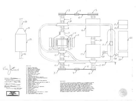
Pneumatic Electric Car Parts List 1. electric slide valve 2. commutator and brushes 3. mid size pulley or sprocket 4. tension pulley or sprocket 5. large pulley or sprocket 6. small pulley or sprocket 7. 1:4 ratio gear set 8. “hall effect” R.P.M. sensor 9. brushes and brush track 10. armature 11. advancing field coil 12. fixed field coil primary generator 13. armature current pick up primary generator 14. pneumatic impeller 15. pneumatic compressor 16. permanent magnetic high voltage generator 17. electric motor 18. belt or oiled chain (oil pump then on number 4) 19. computer control “mapping” 20. battery charger 21. pneumatic pressure tank 22. battery tank 23. piston type electric air compressor 24. automatic transmission 25. electric motor 26. drive shaft 27. pneumatic flow line 28. one way valve 29. max pressure safety valve and p.s.i. sensor 30. 12 volt alternator 31. large pneumatic turbo compressor Description This system is used for an electric automobile. It is intended to provide constant current for continuous operation. The mapping computer allows current from the battery tank to power the primary generators internal electric motor and the electric motor number 17. When the primary generator reaches operating speed it is then feeding current to it’s internal electric motor and current to number 17 (electric motor). This action shuts off current feed from the battery and then number 16 is the charging the battery tank. Number 16 powers the field coil for the primary generator and powers the electric motor number 25 that moves the car. Number 16 will have an adjustable field coil set by the mapping computer to allow the “run away effect” to occur. Number 23 is controlled by the mapping computer referencing sensor number 29. Number 30 powers lights ,horn , radio all 12 volt functions. There will be a flow restriction valve on the flow line into number 15. (valve not depicted)Type your paragraph here.