Compound Wheel
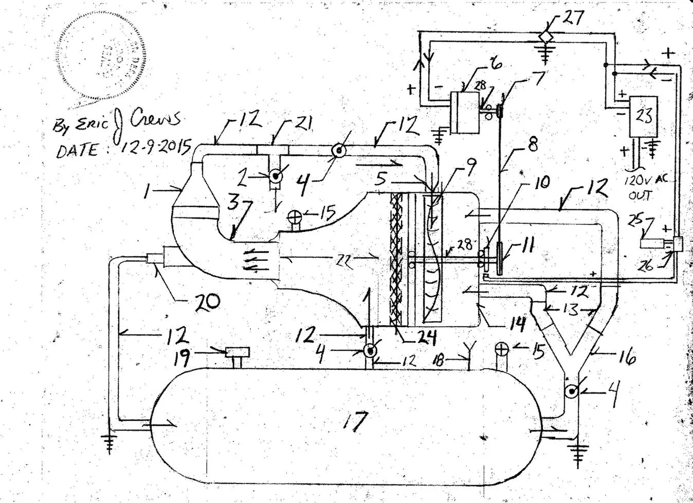
Parts List 1. Funnel 2. Compressor pneumatic pressure purge valve 3. 4″ sewer clean out pipe ( PVC ) 4. Pneumatic valve 5. Pneumatic restriction “tip” / venturi compression tip “funnel” 6. Dynamo ( generator ) permanent magnetic / compound stator ( Ac or Dc systems ) note – the Ac ( alternating current system is for the automotive application and may also be able to cycle the pressure ie. harvest max pressure safety valve exhaust ..and re- circulate the pressure regulated back into the system to then drive electric “active generation” of electricity lunar vehicles 7. Small pulley 8. Drive belt 9. Compound Wheel ( propeller / diameter ) impeller ( circumference ) 10. Hall effect R.P.M. ( revolutions per minute ) sensor 11. Large pulley 12. Pneumatic flow tube 2″ (PVC ) 13. 120 degree bend 2″ PVC tube 14. Kitchen metal pot 15. Pneumatic max pressure safety pressure relief valve 16. 2″….”Y” PVC tube 17. Pneumatic pressure storage tank 18. Pneumatic fill valve one way valve 19. Air pressure gauge 20. Compressor flow system max pressure relief valve / re-pressurized air storage tank 21. “T” union fitting PVC t shape tube 22. Lamp shade made rigid by carbon graphite weave / fiber glass cloth plus epoxy 23. Dc ( direct current ) current to Ac ( alternating current ) electrical power inverter 24. Fiber glass plus epoxy resin union seam 25. R.P.M. rotational rate display 26. Hall effect sensor control circuits 27. Dc voltage regulator 28. Drive shaft O = required bearing race * Note – The electricity generating system is then , for automotive applications , feed current to an electric motor connected to transmission and drive shaft assembly ( 4WD , AWD OR 2WD ) connected to tires…. * Note – The system has many implementation and can be applied also as a starter system for the sealed pneumatic thrust aero space lifting vessels. * Note – Also as an addition to this design the “start” exciter flow tube is identical to flow tube system number 17,12,4,12,22 but differs so that the additional flow pipe becomes number’ s 17,12,4,12,5 then pneumatic discharge then impaling number 9. * Note – As an added safety measure the flow tubes will be wrapped with fiber glass insulation ( 1 1/2 ” ) then wrapped in spiral fashion with Fiber glass cloth plus epoxy resin to the thickness to prevent ( projectile from flow pipe rupture ) approximately 1/2″ of fiber glass cloth plus epoxy resin ( outer pipe shell ie. wrap full pneumatic system… ). Do allow for pneumatic pressure venting via number 15 when wrapping the outer system “shell”…. Additionally a band of carbon graphite ( thermally cured in enclave ) around the outer most shell container to prevent projectile of impeller vane should component failure occur. the carbon graphite ring.. will be then placed around the circumference of the compound wheel number 9 and secured in place by adhesive. * Note – Flow tube number 12 into number 9 is angled so that the the emitted air stream is impaling the vanes of the impeller within the less than 45 degree angle produced by the bend of vane at 45 degrees off of the wheel . the vane is then about 2” long piece of steel that fits within the wheel rim ( steel wheels only ) and is secured by two rivets upon the circumference in the groove of the rim..( additionally …high tensile strength bolt and nut with locking washers securing the vanes will be required for high capacity / high rate of rotation systems ), and two welds upon the top of the piece on the outer circumference of the rim and one weld upon the piece ( impeller vane ) in the groove of the rim . The impeller vane piece then bent at an angle 135 degrees slightly curved on one half of the piece to mate correctly with the circle of the rim.. . If using aluminum rims then the two bore holes will be required (one for rivets the second for two cables then welded tight about 360 degrees upon each vane piece ) to then thread steel cable through the second hole to then be welded to each vane about the circumference one tac weld in the hole then above the bend the second upon the circumference repeated for each vane piece then welds then covered and sealed with epoxy resin to harden a seal. Offset the cable ends at 180 degrees …opposing… * Note – Material selection for the advanced pneumatic electric generating system and components in the pneumatic compression cycle will also be made to last long periods metal components of stainless steel….and generator motor cases then of the lightweight carbon graphite laminate composite with epoxy cured in enclave… will ensure longevity of the motor system then also being easy to repair and will require minimal repair or maintenance cost. The idea is not to make more money by selling products that continue to be a burden upon the customer rather by correct design avoiding planned obsolescence then saving the public money time and inconvenience. * Note – Additionally a “start” pneumatic impeller system connected to a drive pulley can be added to the drive belt system or the additional system can then be made to “free” spin not having a pulley then advancing the drive belt ( causing more pneumatic pressure then vented to the opposite side of the pulley / sprocket system then advancing the generator assembly ) and or the connected to the pulley drive belt system by electromagnetic clutch to allow for variable rotation of the drive pulley. This will allow . The said addition will have a flow tube from number 17 then passing a pneumatic valve ( one inlet one exhaust ) then into the pneumatic impeller in the same fashion as the compressor / impeller wheel ( as depicted below ) with the propeller pulling exterior air through an air filter then … venting through a funnel then through a one way valve with the air pressure directed into the pneumatic pressure storage tank and the exhaust of the additional ” start” impeller then venting into open air..and or through the generator to cool it. The additional compressor / impeller assembly will then be attached to a drive pulley advancing the entire system then only being pressurized from the pneumatic pressure storage tank for a short time period… The addition also changes the dynamics of the system may require addition outer shell thickness increase. The air intake will be coil spring dampened ( suction opens louvers ) . The intake slots regulate intake volume and have ” diffused ” intake as to lower intake pressure per square inch. Upon the additional “start” compressor / impeller assembly the impeller then has two pneumatic air flow injection tubes..one from the pneumatic pressure storage tank the second from the re- introduction of compressed velocity post number 22. * Note – For high capacity / high velocity systems the compressor cases will also be bolted together. with pressure rated gasket … to allow for component replacement ie. bearing races will in time wear…. ( option electromagnetic field bearings aero space …saucer systems) * Note – The valve systems can be actuated manually or by electrically activated solenoid system then controlled by mapping computer / system circuits to control rate and pressure levels and to then cause stable electricity output from main generator number 6. * Note – Additional high voltage generating systems ( also containing Magneto that feeds the Stator in the generator) may be added to the drive belt system ( rotational torque transfer of motion ) may also then be by sprocket and or drive chain assembly then also being then lubricated by non – flammable , non conductive ( electrically ) silicone oil. This allows for an electric vehicle that does not require a storage battery as we have determined that the natural resource and cost of wide scale implementation of battery powered electric vehicles will become cost prohibitive due to the volume of advanced automotive products required to correct the environmental and economic conditions the we face in the future. Just a note about adding the high voltage production generator..a gradual increase of Stator / field coil intensity as then referenced by the rotational rate of the system will be required…it’s then a variable electricity intensity increase to the field coil …with in the high tension generator. *Note – Upon the opposite side of the High Voltage generator will also be places another pneumatic impeller connected to a 1:4 ratio gear set with the high side of the gearing ratio then rotating the generator assembly system to then be fed the “gain” air pressure created by compressor / impeller wheel then connected to the drive pulley…. The pneumatic impeller will allow for pneumatic pressure to counteract the resistance produced when generating electricity and increase the rotational rate of the generator…. The pneumatic flow rate into the generator ‘s pneumatic impeller will also then be regulated by variable valve and the pneumatic impeller’s case will allow for over pressure, pressure release via max pressure safety pressure relief valve ( flow then vents to open air post “cooling” injection flow through the High voltage generator and or into the highest vacuum part of the cycle ie. propeller intake air.., via tube, to draft the generator assembly forward…then also restricting the pneumatic feed flow from the pneumatic pressure storage tanks… ) . The generator and electric drive motor must have open air vents to allow for the o3 (ozone, to escape ..the o3 is not to mix with the flow cycle… The Pulley on the drive belt / drive chain side of the motor system in that rotates in tandem with the generator system is then of a larger diameter by 35 % than the rest of the pulley on the drive belt / drive chain side of the motor system. The pulley / sprocket upon the compressor /impeller drive shaft then about 4″ in diameter and the smaller sprocket / pulley on the dynamo is the 3″ in diameter. *Note – Forced “cold air” injection system by refrigeration system may also augment the High Voltage generator allowing for greater and higher levels of electricity production..also may reduce wear upon the generator itself. * Note – To compensate for the “Baug” rate effect within the high voltage generator when the electric motor connected to the transmission and drive shafts / wheels is electrified, an additional electric motor will be then tandem within the high voltage generator and fed current from the high voltage generator to over compensate counteracting the slowing effect produced when electricity is demanded from the generator by the electric motor / transmission assembly, ..this prevents the system from slowing down and also causes a “load re – active ” generating system then being tilted… * Note – From number 17 the pneumatic flow into number 22 that by passes number 9… then is causing a spiraling of pneumatic flow within number 22 to add to pressure and final rate of pneumatic pressure velocity due to adhesion of pneumatic flow within number 22.