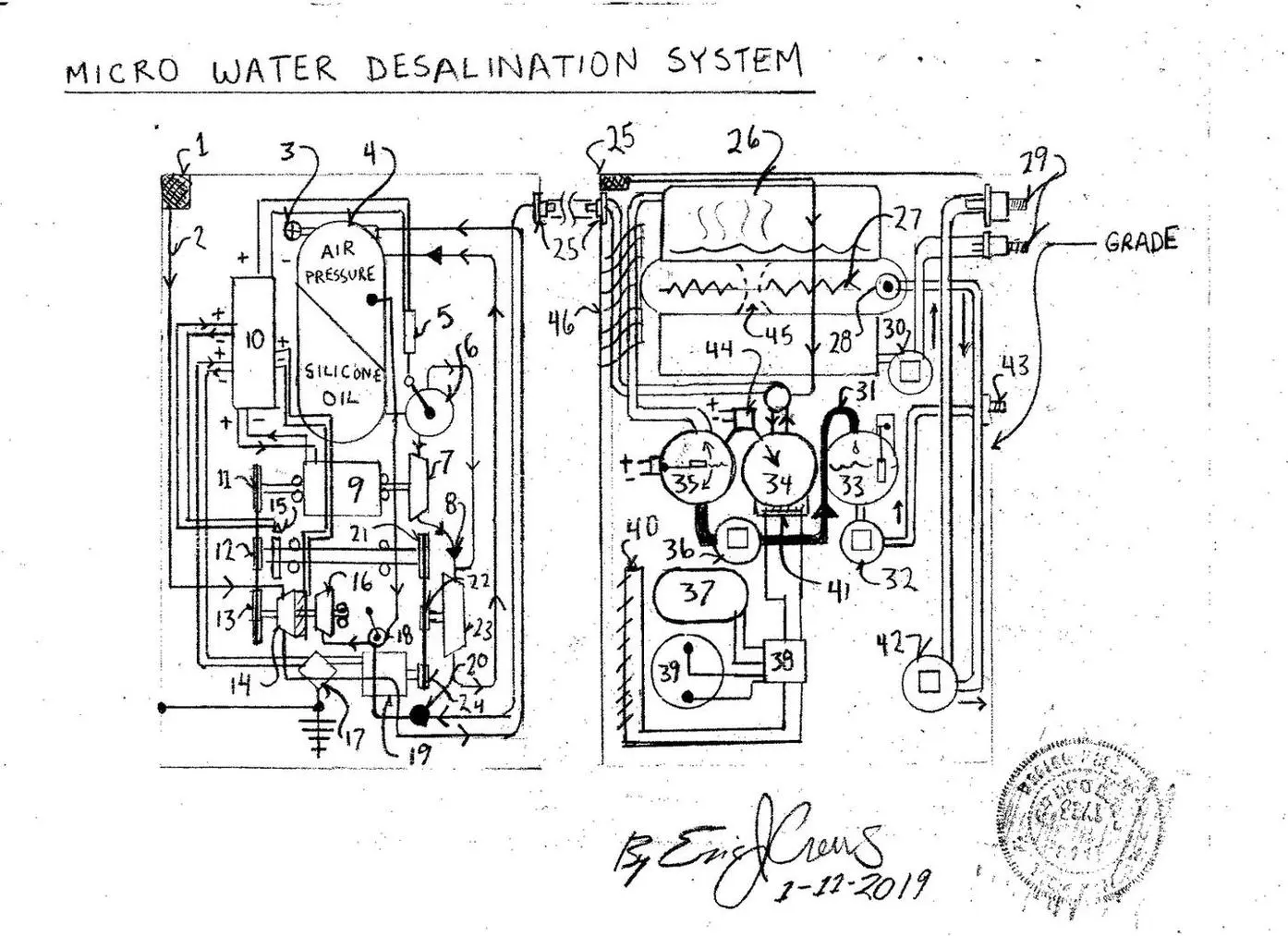
Micro Desalination Agricultural Watering System The following design system is small de salt system for ocean water to then provide cost effect power for removing salt from ocean water for agriculture. The design also will produce excess electricity to then air in pumping the clean water a distance upon a zero emission power free energy power source. The design uses a dual component pressure cycle to then advance a generator to then move water effectively.
Parts List 1. intake air filter “sponge”
2. pneumatic flow tube 3. over pressure / max pressure safety valve “vents over pressure contains sensor when actuated
to “dis engage” the electric clutch upon the pneumatic “air compressor” pump , number 14 4. dual component pressure storage tank 5. flow valve flow direction control solenoid 6. multi path flow valve 7. hydraulic impeller 8. one way flow valve ( hydraulic ) 9. dual shaft electric motor 10. systems electronics “logic circuits” 11. pulley 5″ dia ( diameter ) 12. pulley 5″ dia ( diameter ) 13. large pulley 12″ dia ( diameter ) 14. air compressor 15. R.P.M. sensor ( revolutions per minute sensor ) 16. vacuum pump 17. voltage regulator 18. multi port ( flow type ) “system “Start valve” begins upon stored air pressure then the valve switches position to then cause vacuum to chill the steam produced with in the system 19. generator ( produces electricity ) Ac or Dc current 20. dampener valve regulation valve controls vacuum level 21. large pulley 12″ dia ( diameter) 22. small pulley 3″ dia (diameter) 23. hydraulic pump 24. small pulley 3″ dia ( diameter ) 25. air intake air filter 26. steam chamber 27. electric resistance heat element 28. water heating chamber sensor system contains temperature and pressure sensor also acts as max pressure over pressure safety vent contains pressure fitting for water discharge hose and water level float that actuated the fill system water pump number 42
29. hose fittings / hose couplings 30. salt laden concentrate ( not to be discharged to “open water” ) 31. distilled water flow pipe 32. clean water water pump 33. water ” sphere”contains water pump , number 32 actuation float – contains Ultra violet
internal “clean lamp” 34. negative pressure sphere ( lowering the barometric pressure ( vacuum ) then assist the the condensation process ( insulated thermally ) – contains Ultra violet internal “clean lamp” 35. water collection sphere ( insulated thermal) contains pump actuation float for number 35 – contains Ultra violet internal “clean lamp” 36. water pump also vacuum pump sets the “Start” vacuum negative pressure 37. refrigeration refrigerant ( Nitrogen ) 38. refrigeration master switch block “controls the refrigeration system flow cycles” and water
restriction injector also with directional salt water jet to then “stir” the base of the distillation water
tank. ( the salt water injection valve then retains vacuum in the chamber also assisted by water
vacuum pump, number 36). 39. refrigeration compressor / electric motor 40. refrigeration condenser 41. refrigeration evaporator 42. intake salt water pump 43. distilled water coupling ( out water) also acting as a one way valve 44. vacuum level control switch block unit causes negative pressure ( vacuum in number 35
via tube) contains slide piston to maintain system vacuum in the “run” position 45. water thru channel 46. insulator wrap contains both flow tubes in insulation to then chill the pipes… Description; The above design system the is intended to act remotely and independently of major “metro-plex” to then be able to “de salt” ocean water for agriculture. The final water out flow post number 43 will contain a filter that will require inspection for toxicology at specified interval to then insure that the water is safe. The “line filter” then will be examined for heavy metals / pathogen and chemical contamination to ensure that clean water is used for the agricultural product. The Ultra violet lamps within the spheres then disinfect the internal surface as a “clean function” to then mitigate any growth that could occur from the system becoming effect by “mirco-organism”. In the depiction the total unit then as left and right view connected in a circular “barrel shape” and will be capped with a components dome that contains spear parts with transmitter receiver to then actuate and monitor the system from great distance…. The design then acts as a remote dehumidifier as well then being able to be placed far from the shore line still producing then a well spring for water production. The design will also be able to then be equipped with a “house line” electricity feed that will also then remove the need for batteries upon remote power system / generator systems. This reduces the cost and hazard of using batteries for remote domicile independent “off – grid” living. The above design then may also fill a cistern / holding tank for domestic water use.. the holding tank will include Uv light lamp safety clean lamp and correct filtration. In certain low laying areas flooding becomes a problem. Since this design is partially buried the system will be able to have the ability to be “sealed ” closed ( the intake and out flow can then be shut off so that if flooding is to occur the system can be positioned to close off and remain undamaged by flood waters… In frigid climates the hose coupling and line piping then can be in tandem with electric resistance heating elements to then prevent system disruption from freezing. Since large metro areas upon the coast line in so many regions are in need of clean water these system might work best then as a flotation system with ability to submerge to avoid damage from high storm. The floating desalination water plant then becoming also mobile to be able to aid in disaster regions that have become effected post advent of high storm where the people then need clean potable water.
*