Parts List
- Pulley
- Serpentine Belt
- Power break pump
- Power steering pump
- Air conditioner compressor
- 12v alternator
- Hydraulic fluid max pressure safety valve
- Hydraulic impeller
- Electric motor
- 1:4 ratio gear set
- High speed electric motor
- Permanent magnetic high voltage generator with magneto
- Motor control unit (also controls magneto )
- Hydraulic fluid pump
- Piston pressurized hydraulic fluid reservoir
- Main electric motor
- Transmission / Trans axle
- “Throttle” control unit and circuit pathway box
- Drive shaft from transmission
- Dc to Ac current inverter
- Ac to Dc transformer
- Battery charger
- Battery tank
- Mapping computer / logic box
- Throttle cable
- R.P.M. sensor wire “bus”
- Wire “bus” to logic board / mapping computer
- Wire “bus” to instrument cluster and ignition switch
- Hydraulic flow tube
- Max pressure hydraulic fluid safety return tube
A = connecting drive shaft
O = Required bearing race
Description;
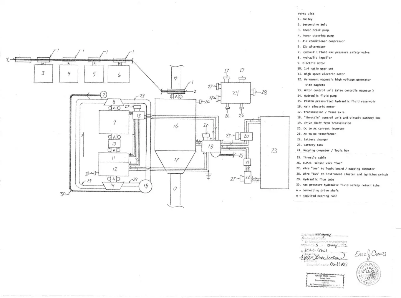
From the ignition switch the inverter number 20 is activated feeding current to numbers 20, 18,13,9 and 11 . Number 12’s output feeds circuit in number 18 pre variable resistor that controls current level into number 16, main electric motor. There are four branching circuit pathways into the variable resistor in number 18 ;
1. “jumper circuit” that reintroduces a higher current level back into number 13.
2. The battery charging circuit that feeds the Ac to Dc current to transformer then battery charger then charging battery.
3. In addition the main charging path current from number 12 to number 18.
4. Battery feed current circuit
Current post variable resistor in number 18 feeds number 16 Main electric motor.
The velocity of the hydraulic assembly is controlled by the mapping computer and references the R.P.M. sensors.
Number 9 rotates once for every four rotations of numbers 11 and 12. The magneto in number 12 is controlled in number 13.
Number 24 also controls the battery charging system.
Numbers 3,4,5,6, have a belt drive system with tension pulley depicted but not listed.