Vacuum Wagon
Today there are so many internal combustion engines systems in gasoline powered automobiles . The quick solve is to the use existing cars with a quick conversion as many people can not afford a new car… the engine exchange system with a Vacuum type electrical generator that is an “Active system to produce fuel less electricity may in fact be the solve since we all are racing the clock on the Carbon dioxide problem.
The design system uses the existing gas tank then converted to an oil catch tank with a vacuum therein. the oil will then be a non conductive non flammable silicone oil the additional “Active generator system is then placed in the trunk of the vehicle and will feed the installed electric motor then rotating the stock transmission that the car cam equipped with.
The upgraded vehicle should then meet all required safety standards then with the capacitance for static electricity Produces by air / oil flow) dealt with in a plasma box the allowing for capacitor to cause an electrical arc discharge between electrodes and also be contained in an inert noble non conductive
gas ( Argon ) then also as a fully electrically insulated container.
The following design system is the the conversion platform to yield an unlimited range electric automobile.
The system may also work with only Pneumatic pressure.
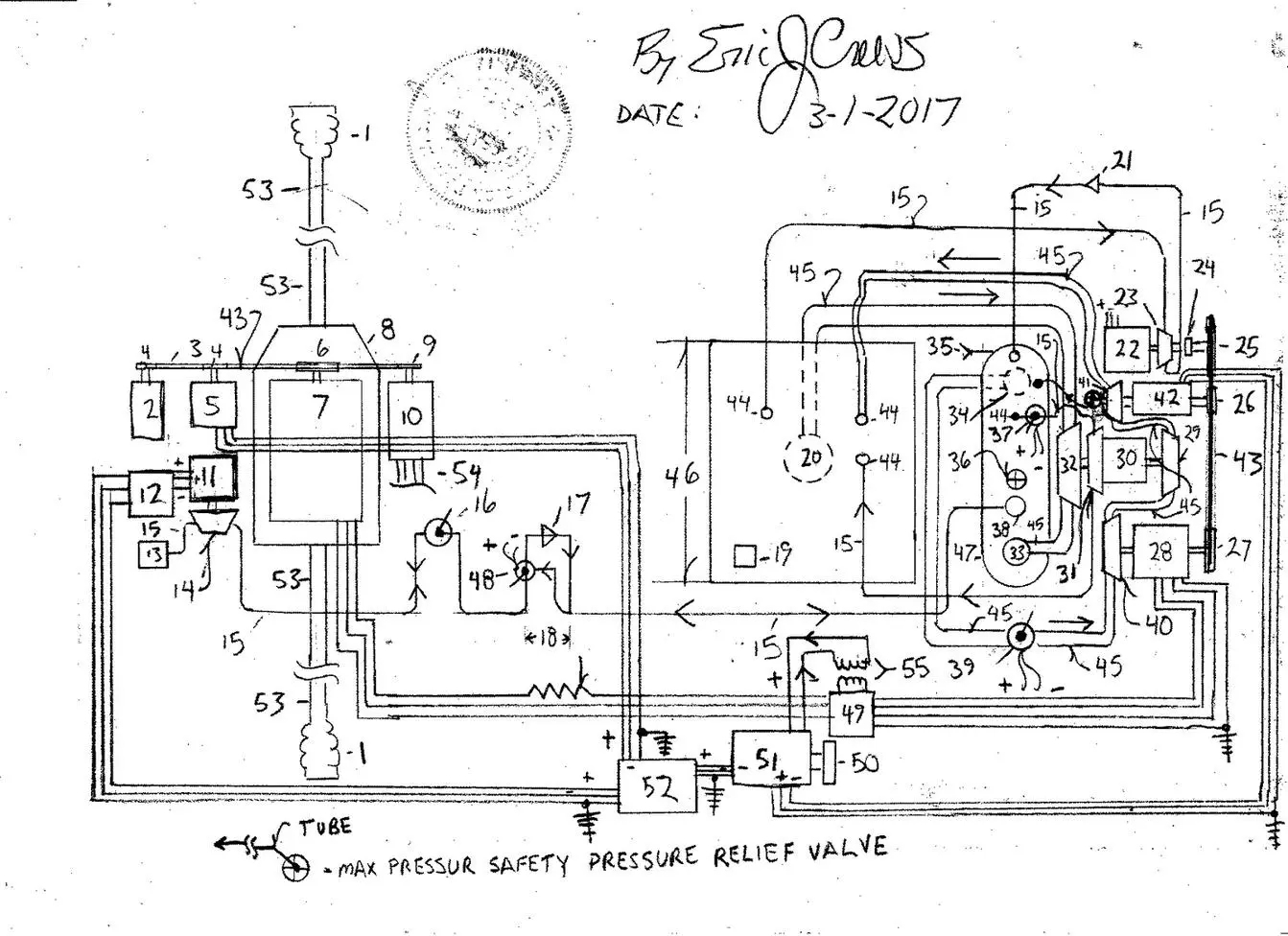
Parts List
1. C.V. ( “constant velocity” ) drive shaft joint boot
2. power steering pump also containing pump system for the breaks hydraulic pressure ( redundant sum of two required!
3. drive belt
4. pulley
5. alternator / 12vDc ( direct current )
6. main drive pulley
7. main high voltage electric motor connected to the automotive transmission by internal drive chain with main drive pulley then causing the drive belt to rotate
8. automotive transmission
9. pulley
10. electric clutch with air conditioner compressor
11. dynamo permanent magnetic generator 12v Dc or 24v Dc Also as a motor if powered
12. Dc to Ac power inverter
13. air filter
14. pneumatic impeller
15. high pressure tube
16. Manual and electric “Start” valve
17. one way valve
18. flow direction
19. Air inlet dampener restricts air intake
20. oil drain
21. one way valve
22. 1:8 ratio gear set high side to number 23 ( the internal low side then as also a speed regulator via resistance of an feed current into it’s internal electric motor a ” speed balencer ” system breaking mechanism / electric motor low power drag increase…produces resistance at safe levels
23. high speed vacuum producing air pump
24. R.P.M. sensor ( revolutions per minute )
25. large pulley
26. small pulley
27. extra large pulley
28. High voltage generator with permanent magnet magneto to feed the generator stator / field coil
29. high speed hydraulic pump
30. 1:10 ratio gear set high side to number 29
31. hydraulic impeller
32. large circumference hydraulic pump internal 1:20 ratio gear set with the “20” then being tandem rate of rotation with the pump wheel
33. oil return port
34. oil drain
35. one way pneumatic fill valve
36. max pressure safety valve also as a oil fill port with dip stick.. vents excessive pneumatic pressure
37. hydraulic flow valve electric also part of the safety regulation system if fault occurs a flow restriction valve actuation by sensor referencing the r.p.m. sensor
38. pneumatic fill / or exhaust port
39. hydraulic flow valve restriction valve governs the speed of the “Active” generator system final electricity output
40. Hydraulic impeller
41. Hydraulic impeller with max pressure safety pressure relief valve feeds over pressure back to the combined component pressure storage tank
42. Electric motor ( 20+ Hp / horse power)
43. drive belt
44. hydraulic intake port
45. large diameter flow tube
46. Stock automotive gas tank then converted into a vacuum chamber
47. Combined component pressure storage tank ( air pressure above silicone oil)
48. Pneumatic flow direction switch valve
49. Voltage regulator
50. Multi wire “bus” ribbon wire connector to the instrument cluster / dash board controls)
51. System electronics control “bay” contains mapping / logic circuits for the generator’s control
52. Secondary Dc to Ac electricity power inverter
53. Drive shaft
54. tubes to the refrigeration system for the cabs air conditioning system
55. Electric transformer from high tension 240v Ac to lower tension 120v Dc current for the generators electric motor, number 42 .
* Note -The vehicle lighting system radio horn turn signal lamps etc…are all powered by the 12v Dc alternator with redundant circuit path to compensate for belt break / belt failure by an additional transformer within the electronics “circuit bay”.
* Note – Percentile of generated electrical current in number 28 is then fed to number 42 to then advance the “zero point” of the field pressure allowing the system to produce a “baug” resistant electric power ban to cause sufficient electricity then produced in the generator to sustain the rotational rate when loading is placed upon the generator by the forward main electric motor , (number 7), that is connected to the transmission.
The design system pumps oil back into the combined component pressure storage tank faster than it is discharged while generating electricity.This causes sustained electricity delivery to propel an automobile constantly and will never require pressure charging as the system can also use number 12 as a motor to then compress air into the pressure storage system.
Additionally the system contains pressure sensors for fluid pressure and pneumatic pressure upon the tube couplings ( pipe fittings) the sensors to feed information to the circuit logic control system to govern the generator ( also measuring the vacuum negative pressure and positive pressure in the combined component pressure storage tank.