Vacuum Draft Hydraulic Compound Automotive Motor
The following Automotive Motor system is a perpetual motion fuel less battery less electric hybird automotive Motor system yielding on demand service with unlimited range. The design is then a “draft idler” system yielding the system to “diesel” upon the produced vacuum then advancing by the produced generated electric current within the generator system. The design “Starts” then with pneumatic pressure and has the ability to automatically replace the displaced “start” air pressure. The Motor is also a magnetic bouncer then using electromagnets within the piston system.
The design uses the motion of the piston to also pump air upon the down stroke to then advance the generator into forward rotation then producing more electricity to electrify the contained electric motor system connected to an automotive automatic or manual transmission. The system will also work without the electromagnetics upon piston system but requires a deeper vacuum still requiring the piston and valve system as depicted, ( this would lower the cost of manufacturing ).
The design then operates by pulling a greater vacuum upon each down stroke of the piston system via valve systems numbers 9 and 11. The down force then obtained by the pistons cylinder head’s electromagnets “firing” yielding exhaust air pressure from under the piston ( or while in down ward motion caused by the adjacent piston ) to then exhaust and impale a pneumatic impeller causing greater rotational rate upon the ratio gear set and generator assembly. The resultant air pressure then entering the air filter and may cycle then entering the intake valve system number 66 to allow air in under the piston also relieving the suction effect during the up stroke of the piston.
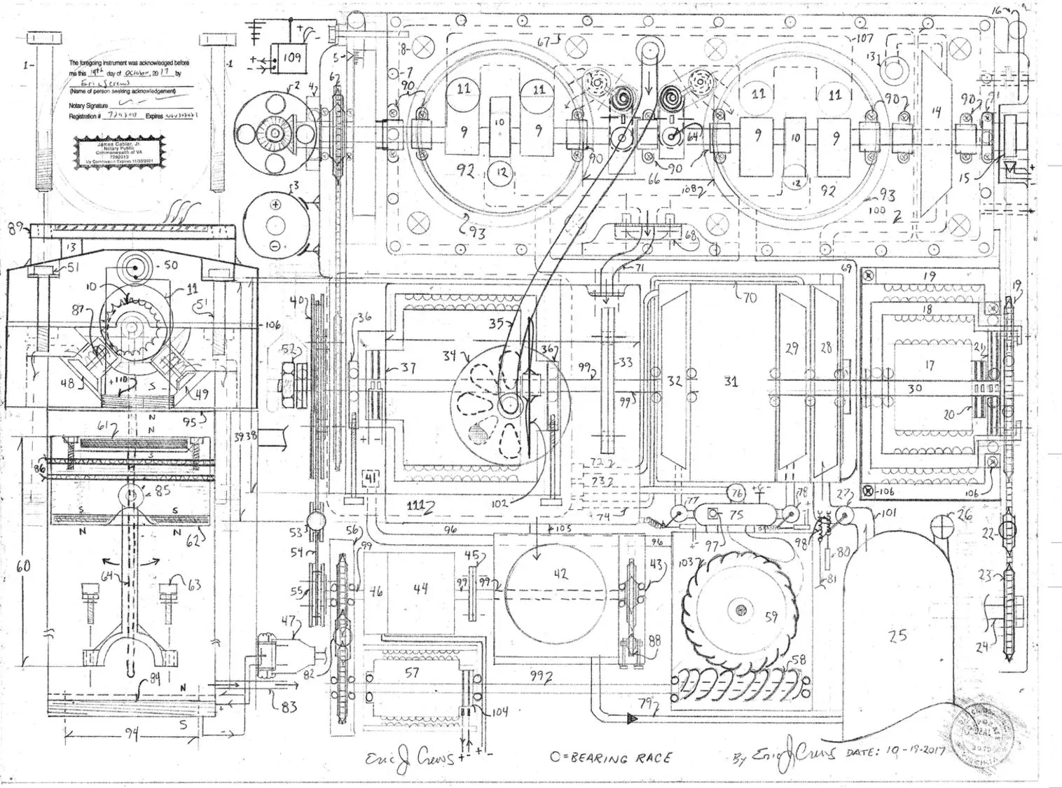
Parts List 1. cylinder head Head Bolt 2. automotive ignition distributor 3. Automotive ignition coil 4. oil seal end bearing cap ( sealed bearings) 5. distributor timing marks with lamp view port ( “harmonic balancer” ) 6. crank shaft and cam shaft sprocket and drive chain system 7. oil pan mounting bolt bore 8. cylinder head bolt bore threaded 9. cam lobe ( vacuum producing large valves ) 10. cam lobe ( piston lifting “Up suck” valve actuated on the up stroke of the piston 11. vacuum producing valve large valves and valve system oil seals and expansion spring opens on the down stroke of the piston piston down stroke caused by the electromagnet in the cylinder head firing also compressing the air under the piston venting to the pneumatic impeller 12. up suck valve causing negative vacuum “well” to open an lift the piston up ward 13. pneumatic vent tube – allows air post pneumatic impeller to enter the air intake manifold number 89 14. pneumatic impeller 15. R.P.M. ( revolutions per minute) sensor 16. piston system oil pan dip stick level 17. inner electromagnetic clutch or inverse electric motor so that the armature is then the outer
circumference ( inner diameter of number 18 ), with the stator then the core / center of the unit 18. outer electromagnetic clutch and larger circumference electric motor armature 19. main electric motor Stator / Field coil – the field coil is then motivating the main electric motor’s armature tandem sprocket 20. inner electromagnet clutch brushes and brush track 21. electric motor commutator 22. drive chain tension sprocket 23. sprocket tandem rotating with the input shaft to an automotive transmission system ” automatic or manual” 24. drive shaft 25. pneumatic pressure tank 26. over pressure safety pressure relief valve 27. main pneumatic “start” valve 28. pneumatic impeller 29. hydraulic impeller 30. ratio gear set low end “torque input drive shaft tandem rotation with numbers 28,29 and 30 31. 1:10 ratio gear set with dual internal electric motors ( one electric motor high side tandem armature
connection – one electric motor low side tandem armature connection / the drive shafts are in union) 32. hydraulic impeller tandem rotating with the out put of the ratio gear set the “10” of the 1:10 ratio gear set 33. bolt plate 34. vacuum tank regulator vacuum dampener with vacuum level sensor and sensor fault indication circuit 35. vacuum flow tube … 36. generator drive chain tension adjustment screws 37. generator commutator / and electrical transference “brushes” 38. Main generator ( with permanent magnet magneto) 39. Main vacuum tank ( negative air pressure) 40. pulley and tandem locked sprocket system 10 ” dia ( diameter) 41. oil intake within the second oil pan 42. air compressor ( pulls intake air from air filter atop the unit ) contains electric air intake selection switch valve to
the compress ambient exterior air or air intake from the vacuum tank
43. drive shaft to rotate the air compressor 44. ratio gear set 1:4 ratio high side rotation toward the air compressor 45. bolt plate 46. mechanical clutch electric actuation referencing the systems stored air pressure ( the air compressor is not required to “run ” all the time) 47. electromagnet wire weather safe electrically insulated boot – electricity insulator sheath 48. large valve ( causes vacuum when the electromagnet in the cylinder head “fires” – open upon the down stroke 49. up suck valve ( open upon the up ward travel of the piston ) 50. wire port for the upper cylinder head mounted electromagnet system sum of two 51. valve cover bolts 52. nut 53. tension pulley adjust the drive belt tension 54. drive belt 55. small pulley 4″ dia ( diameter) 56. oil retainer casing 57. permanent magnetic dynamo 58. worm gear oil pump drive screw gear 59. oil pump and oil filter 60. magnetic equipped piston ( sum of two for this system) 61. rare earth magnet fixed magnet 62. rare earth magnet fixed magnet 63. piston rod lock bolts 64. oil conduit push rod – moved the inverted valve system , number 66 sum of two 65. 66. valve system sum of two allows air in under the piston upon the up stroke of the piston with the valve to then be closed upon the down stroke of the piston to then compress the air and be directed to the systems pneumatic impellers… the pneumatic impellers then being number 28 upon the generator assembly and number 14 upon the piston system 67. “in head” vacuum manifold ( left ) 68. up suck valve head exhaust transference mounting surface sum of two threaded bore holes to bolt suction tube, number 71 69. under piston air pressure discharge tube contains a one way valve for the air flow prior to entering the pneumatic impeller number 28 70. oil exhaust tubes from both oil / hydraulic impellers returning oil to the second oil pan 71. suction tube rated for high vacuum / may contain flow dampener variable adjustment valve then referencing
total vacuum in the main vacuum tank to quicken negative pressure level 72. oil return tube / coupling 73. oil return tube / coupling from oil pressure manifold pressure regulation safety valve 74. oil return tube / coupling 75. oil manifold 76. oil pressure regulator valve safety valve – vents oil pressure into second oil pan 77. oil control flow valve electric redundant and safety fault “all stop circuit function cross references oil pressure sensor upon the oil pressure manifold 78. oil control flow valve electric redundant and safety fault “all stop circuit function cross references oil pressure sensor upon the oil pressure manifold 79. pneumatic pressure flow pipe containing one way flow valve “to the pneumatic pressure storage tank , number 25 80. solenoid electric control for the pneumatic start cycle valve control 81. manual sheathed cable valve control 82. drive chain tension sprocket for drive chain and sprocket system 83. pneumatic discharge coupling air flow enters number 69 84. in cylinder “base electromagnet” fires just after the piston bottoms out and begins upward travel 85. hinging wrist pin ( joins the piston to the piston “rod” 86. piston rings and oil rings 87. valve expansion springs ( upon all valves in the cylinder “head” ) 88. air compressor drive chain tension adjustment screw positioning screws 89. air filter and air intake manifold 90. over head cam bearings – lubricated thru in head channel 91. end cap bearing with oil seal ( left and right sides…) 92. piston cylinder 93. stain less steel cylinder liner ( carbon graphite / epoxy engine block” ) 94. inner dia of the base electromagnet 95. head gasket 96. oil flow tube 97. oil manifold main lubrication exhaust ports lubrication of all casing and moving marts then from the coupling 98. re-tension spring 99. drive shaft 100. cylinder “in head” pneumatic flow manifold 101. main pneumatic flow pipe from pneumatic pressure storage tank to start valve from start valve to the start cycle pneumatic impeller , number 28 102. generator cooling fan 103. circumference gear driven by the screw gear 104. dynamo brush track electric transference “brushes” 105. one way valve and flow pipe combination unit – allows air pumped from the vacuum tank until the vacuum dampener number 34 is actuated then disengaging the electric clutch for the air compressor unless air pressure is require in the main pressure storage tank for subsequent system re- start 106. valve cover gasket 107. “in head” vacuum manifold ( right) 108. “in head” vacuum manifold up suck valve system 109. Plasma box static electricity electric arc discharge and residual electricity harvesting system to then reintroduce harvested electricity from the plasma back into the system. system electrical ground.
Description
The valve system number 66 is then an inverted valve system also actuated by the over head cam then using push rods within the system to allow air , from the air filter into the piston chamber under the piston while the piston is traveling upward.
The push rods then also act as a lubrication conduit for the cam lifters and and rocker assembly. The channel also lubricates the valve cam bearings and crank shaft main bearings ( main bearings the upon a diametric opposed crankshaft with the orbital rod bearings at zero and 180 degrees connecting to the piston rod bearing .
The electric motor number 19 then has an expanded armature containing an internal electromagnetic clutch. The division between the two function of the system must then be insulated magnetically so that magnetic field integrity is retained.
Valve number 12 is then the “Up suck” piston valve to then pull the piston up ward by the greater vacuum produced by the over head valve and cam system numbers 9 and 11. Number 11 is then the tappet covering the in head valve number 11 depicted upon the side view then with the cam showing the full open point for number 11.
The ratio gear set , number 31 then being the ratio of 1:10 oriented so that the “10” then being the “high side” of the ratio gear set , tandem rotating with the generator number 38. Number 38 then produces the current for the main electric motor, electric clutch and electromagnets contained within the piston chamber and the cylinder “head”.
All drive chain encasements then fed oil pressure from number 97 to send and return flow tubes … the “send” then emanating from number 97 with the return flow tubes then to the oil recovery oil pan… number 111.The tube number 35 then connected to the vacuum dampener inlet valve , number 34, then is pulling greater vacuum in number 39 vacuum tank, with the down stroke of the piston the arrow from the “in head manifold” number 67 shows air inlet from number 89 into the inverted valve assembly , number 66.
The “up stroke” suction resistance pressure is relieved by open valve within number 66…
Number 69 then contains a one way valve upon the piston produced air pressure as not to cause a back flow ..then allowing air only into the pneumatic impeller , number 28.
Number 29 is then a hydraulic impeller tandem rotating with the input drive shaft into the ratio gear set . Number 32 is then a tandem rotating hydraulic impeller rotating to counter tilt the resistance pressure in the ratio gear set. Both hydraulic impellers then controlled by electric valves upon the oil manifold number 75 by electric positioned
valves ( solenoid controlled ) then referencing the R.P.M. sensor , number 15..
The distributor , number 2 then is implementing the use of contact points to transfer electricity via rotor to the wires that connect to the electromagnets will also have locking nut base and base plate. The system is timed by number 5.
Number 3 is the ignition coil that changes the current level to high energy discharge for the magnetic system.
Number 57 is a permanent magnetic 12v dynamo then feeding current to the ignition coil.
The air pressure exiting number 28 is then channeled via tube to number 14. Number 14 is a pneumatic impeller then tandem rotating with the over head cam within the cylinder head.
Vacuum dampener valve, number 34 then with screened air inlets upon the under side of the valve, will remain closed until the vacuum tank, number 39, has reached sufficient negative pressure ( “vacuum” ) to then counter act the total systems resistance drag torque.
The drive shaft then from the generator , number 38, may then have an electromagnetic or disk clutch installed between the generator and the drive pulley / sprocket assembly, number 40. This allows for the generator to climb
in R.P.M. ( revolutions per minute) to yield the generator at high electricity out put levels. Number 31 may also contain dual electric motors then upon each side of the ratio within the ratio gear set, number 31, the additional electric motors armatures then being tandem locked to the input and out put drive shaft’s of the ratio gear set.. an “electric counter tilt” method. The pulley and sprocket, number 40 then are tandem locked and rotate in unison.
The dynamo then voltage regulated for the components that require the 12v systems horn lights radio etc… also as a boost circuit the electromagnetic may then be increased by dual wound electromagnets then fed high electricity levels by a percentile of the generators , number 38 electrical out put post voltage regulation.
Note – The final casing the coated to then be electrically insulated and encased within a pressure check envelope to check for electrical insulator integrity. The system does not electrically ground to the chassis of the vehicle. Also the drive shafts to the wheels the have non electrically conductive connector to also keep the drive shafts out of weather and water exposure.
Note – the main generator’s stator current feed can be obtained from the ignition coil as a stepped up
current level ( voltage) this allows for higher intensity electrical output from the generator the circuit
will also require a voltage regulator before entering the stator of the generator.
Note – the generator’s produced current the directed via tandem circuit with multiple variable
resistors / potentiometers to then engage the electric clutch , increase electricity to the main
electric motor, and engage the electric “counter tilt in number 31 then increasing the current to
the piston system electromagnets simultaneously. This is then the “throttle” circuit.
Note – a non flammable non electrically conductive synthetic oil will be used for this system.
Note – additional burst casings ( flow tubes) and shock shield ( motors, impellers, gear set and, generator)
for component manufacturing failure then installed in the correct location to avoid injury from
manufacturing defect causing system failure