Vacuum Drive Accelerator
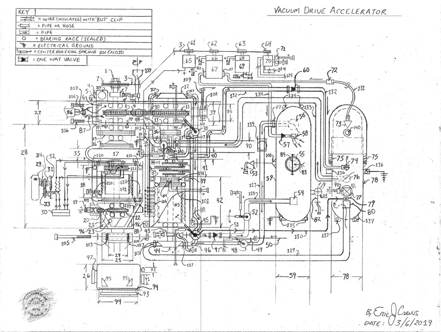
The Vacuum Drive Accelerator is an advancement in automotive power plants . The system acts an a fuel less generator for an unlimited range electric vehicle. No battery required.
Parts List
1. Nut
2. pulley
3. drive belt
4. oil drain spout
5. oil drain valve
6. drive chain casing vent with air screen mesh resist water inumndation
7. R.P.M. sensor ( revolutions per minute sensor)
8. drive sprocket
9. tension sprocket (adjust the drive chain’s tension)
10. drive chain
11. large sprocket – tandem rotating with the high side of the ratio gear set
12. hydraulic pump – pump internal “pump wheel ” tandem rotating with the high side of the ratio gear set
13. union bolt plates
14. pipe coupling
15. union bolt plates
16. torque converter mounting plate ( sum of 8 bolts about 360 degrees – from the center point)
17. torque converter
18. Main electric motor ( Hp “horse power” rated for the total weight of the motor vehicle / automobile )
19. Automotive automatic transmission link chain / drive chain tension adjustment bolt with lock nut to set the screw)
20. transmission drive chain ( lubricated via transmission fluid / encased) and sprocket
21. transmission drive chain
22. dual shaft electric motor ( number 18 ) output shaft tandem rotating with the automotive automatic
transmission sprocket
23. automotive automatic transmission gear selector and end shaft retainer (contains sealed bearings) threaded
bore and bolt sun of two mirror line from the center line
24. automotive automatic transmission mounting assembly non electrically conductive bushing
25. automotive automatic transmission mounting assembly mounts to the chassis
26. electronics “bay” power management components voltage regulators / automotive / “fuse box” / system
electrical relay panel / motor “logic” system rate control electronics with venting high wall intake low above
the recess lock dock in number 96 – this keeps the electronics cool….
27. drive chain and sprocket transfer case – contains lubrication oil and is a “vented” casing ( front )
28. main electric motor and automotive automatic transmission assembly ( bolt union into threaded bore)
29. foot pedal accelerator pedal
30. main electric motor multi wire ( insulated ) wire “bus” clip
31. throttle roller gears ( positions the potentiometer )
32. dual retention coil springs
33. potentiometer roller gear ( positions the potentiometer)
34. roller gear lever and foot pedal linkage
35. torque converter “swell contour” encasement “torque converter outer housing”
36. hydraulic fluid ( hydraulic fluid dampener valve )
37. pipe coupling
38. hydraulic fluid divergence valve ( allows the back pressure from the oil exiting the hydraulic
pump , number 12 to then vent to the ratio gear set’s high side – output rotation , hydraulic impeller thus
reducing the resistance produced when using a ratio gear set.
39. drive chain and sprocket transfer case – contains lubrication oil and is a “vented” casing ( rear )
40. ratio gear set’s high side tandem rotating hydraulic impeller
41. ratio gear set 1:40 ratio gear set
42. compound p.m. ( permanent magnet ) high voltage generator ( wound stator / field coil core permanent magnet )
43. R.P.M. sensor ( revolutions per minute sensor)
44. hydraulic impeller – tandem rotating with the rotational input side of the ratio gear set
45. hydraulic fluid “back pressure” safety valve – also an electric divergence flow control valve to then allow
the re-pressurization of the dual component ( hydraulic fluid under air pressure ) pressure storage tank contains oil pressure sensor reporting to the system’s logic processor helps adjust the valve
46. flow union pipe ( balance pipe)
47. one way valve
48. start valve with sheathed manual pull cable connects to the automotive ignition 9 also used when shutting
the system off then using the electric solenoid ( with internal coil spring ), to close the valve – the valve
also closes when the electronic circuit logic processor within number 26 has determined that the dual
component pressure storage pressure tank , number 59 has reached sufficient oil and air pressure for
the subsequent system “re-start”.
49. sheathed “pull cable” mounting bracket
50. sheathed braided stain less steel pull cable ( graphite lubricated )
51. electric solenoid with internal coil spring ( retention to the valve ” closed position” ) clarifies direction
of the solenoid actuation electrified the solenoid closes the valve retracts toward the front of the vehicle
52. oil flow control valve causes the oil flow back pressure to then vent to the vacuum chamber via safety
pipe , number 130
53. oil pressure sensor electric ( connects to the logic processor , number 26 for system’s correct operation )
54. oil return coupling then caused by valve position , number 45’s position
55. oil fill screw cap ( threaded / pressure rated )
56. oil drain
57. one way valve
58. pneumatic pressure return coupling
59. dual component pressure storage tank , hydraulic fluid – non electrically conductive non flammable
hydraulic fluid – (silicone oil) and air pressure pressure storage tank
60. one way valve
61. pulley
62. pulley
63. pulley
64. pulley
65. 12v Dc alternator
66. electric clutch
67. vacuum pump
68. electric clutch
69. air conditioner compressor
70. power steering and power break pump ( a dual pump unit )
71. power steering and power break pump power steering fluid / break fluid reservoir with fluid level sensor indicators
upon the fluid fill screw caps
72. rigid pipe flex vacuum hose coupling union
73. one way vacuum valve
74. oil return coupling
75. vacuum chamber collapse dampener expansion coil spring ( the two halves of the vacuum chamber
are interference fit )
76. oil drain ( oil under high vacuum out flow coupling / pipe fitting)
77. vacuum level safety exterior air inlet dampener valve
78. vacuum chamber
79. high pressure oil flow return coupling
80. main line oil return coupling / pipe fitting
81. pneumatic over pressure pressure relief safety vent valve ( vents over pressure to the exterior of the system
82. pneumatic pressure sensor – reports to the system’s logic processor number 26
83. pneumatic one way fill valve mounts to the oil fill screw cap
84. safety rod retains the oil fill screw cap as a safety measure hinged mounting to the dual component
pressure storage tank
85. drive chain casing mounting assembly mounts the system to the “fire wall” of the vehicle
86. drive chain casing mounts the assembly to forward part ( front cross member ) of the chassis
87. drive chain casing mounts directly to the drive chain casing rectangular bolt pattern threaded bore
upon the drive chain casing
88. high voltage generator mounting bore
89. high voltage generator mounting bore
90. Magneto ( feeds electricity to the stator field coil of the main high voltage generator) contains commutator
and roller wheel contact brushes – the electricity output is voltage regulated before the stator of the main
high voltage generator is electrified upon the circuit
91. multi wire “ribbon wire” instrumentation ( to the dashboard ) wire “bus clip”
92. multi wire “ribbon wire” – wire “bus clip” docks the drive belt driven electrical components
93. multi wire “ribbon wire” – wire “bus clip” docks sensors of the system also docks valve control solenoid
wires with hinged weather proof “lid” and 12v Dc automotive “fuse block” for the automobiles
amenities ( horn , lights, radio, power windows, etc…)
94. weather safe fuse block “lid”
95. inlet air vent also as a protrusion to then dock into the recess number 96 for stable mounting with
push / release safety tabs
96. docking recess for the base of number 26 electronics bay
97. multi wire “ribbon wire” main electrical power “feed wires “to” the main electric motor , number 18
98. vacuum level sensor – reports to the system electronic control circuits in number 26
99. drive chain housing mounting bolts (with lock washer) into threaded bore upon the component
number 28 – sum of 8 bolts total in a rectangular pattern
100. oil pressure sensor threaded mounting bore
101. high voltage generator armature roller track and stabilizer sealed bearings ( high heat tolerant
lubrication ) stabilizes the armature’s rotation about the core drive shaft
102. voltage regulator
103. electrically non conductive bushing
104. nut and lock washer assembly
105. system mounting bolt
106. Number 87’s mounting bolt
107. hinged fitting contains non electrically conductive “bushing” same format as number 24 & 25
108. drive chain housing mounting hinged fitting contains non electrically conductive “bushing” same format
as number 24 & 25- mounts to the fire wall
109. mounting bolt and nut assembly contains lock washers nut side and flat washer bolt side
110. magneto commutator and “roller” contact brush contact electrical current transference contact points
111.
112. ratio gear set lubrication oil fill and drain plug
113. compression pipe fitting
114. main high voltage generator commutator and “roller wheel” contact brushes
115. main high voltage generator armature
116. permanent magnet and electromagnet ( main high voltage generator stator / field coil )
117. pipe coupling
118. union bolt plates contains sum of six bolt – flat washer – lock washer and nut assembly
119. oil fill screws cap with oil level dip stick and oil level indents
120. main electric motor mounting bores
121. main electric motor armature
122. main electric motor commutator
123. magneto “roller wheel” electrical contact points
124. power steering power steering fluid flow pipes
125. power break break fluid flow pipes
126. air conditioner refrigerant flow tubes
127. start cycle oil flow pipe
128. oil flow pipe refills the dual component pressure tank for subsequent system re-start
129. main line oil return pipe ( to high vacuum )
130. high pressure oil return oil flow pipe – safety pressure relief pipe
131. high vacuum vacuum flex hose
132. “ratio gear set’s “counter tilt” oil return oil flow pipe
133. main oil flow pipe
134. pneumatic pressure fill pipe
135. mounting bore
136. mounting bore with electrical ground
137. mounting bore
138. main high voltage generator commutator
139. oil filter and oil filter housing upon the flow pipe number 127 and drive shaft receiving cup then upon
both out put of the automotive automatic transmission
140. oil fill (vacuum level rated ) screw cap
Description
The above design system causes the wick of hydraulic fluid under ( exposed) to high vacuum causing the electricity producing magneto and generator to yield high density high voltage electricity. The high density high voltage electricity is then applied to a dual shaft electric motor that rotates an automotive automatic transmission then being able to rotate the wheels of an automobile.
The system effectively will “diesel” ( continue to “run” ), on vacuum then using pneumatically pressurized hydraulic oil ( silicone oil ) to begin it’s rotation then on board vacuum then , after the vacuum chamber is at operating range will allow air in to then be compressed by the exhaust of the vacuum pump to re-pressurize the dual component air pressure hydraulic fluid pressure tank causing oil pressure to allow the system to begin it’s rotation.
The design is an electric automobile that requires no battery and will provide “on-demand” service 24 / 7. The motor system then being a suitable replacement for the duty / service requirement of current internal combustion engine systems will be able to replace fossil fuels for transportation correcting the environmental CO2 ( Carbon Dioxide ) / Climate Change / Global Warming problem.
The design is a zero emission electric car! (no fuel required!)
*