The Lunar Orbit Stabilization System
The Lunar Orbit Stabilization System melts lunar surface regolith via Carbon Dioxide laser, to then act as an anchor then tethering a sealed force vectoring electric hyper jet that applies lift to the surface of the moon. The design then intended to arrest the moon’s orbital escape. The design uses a fuel less electricity generator to power it’s systems.
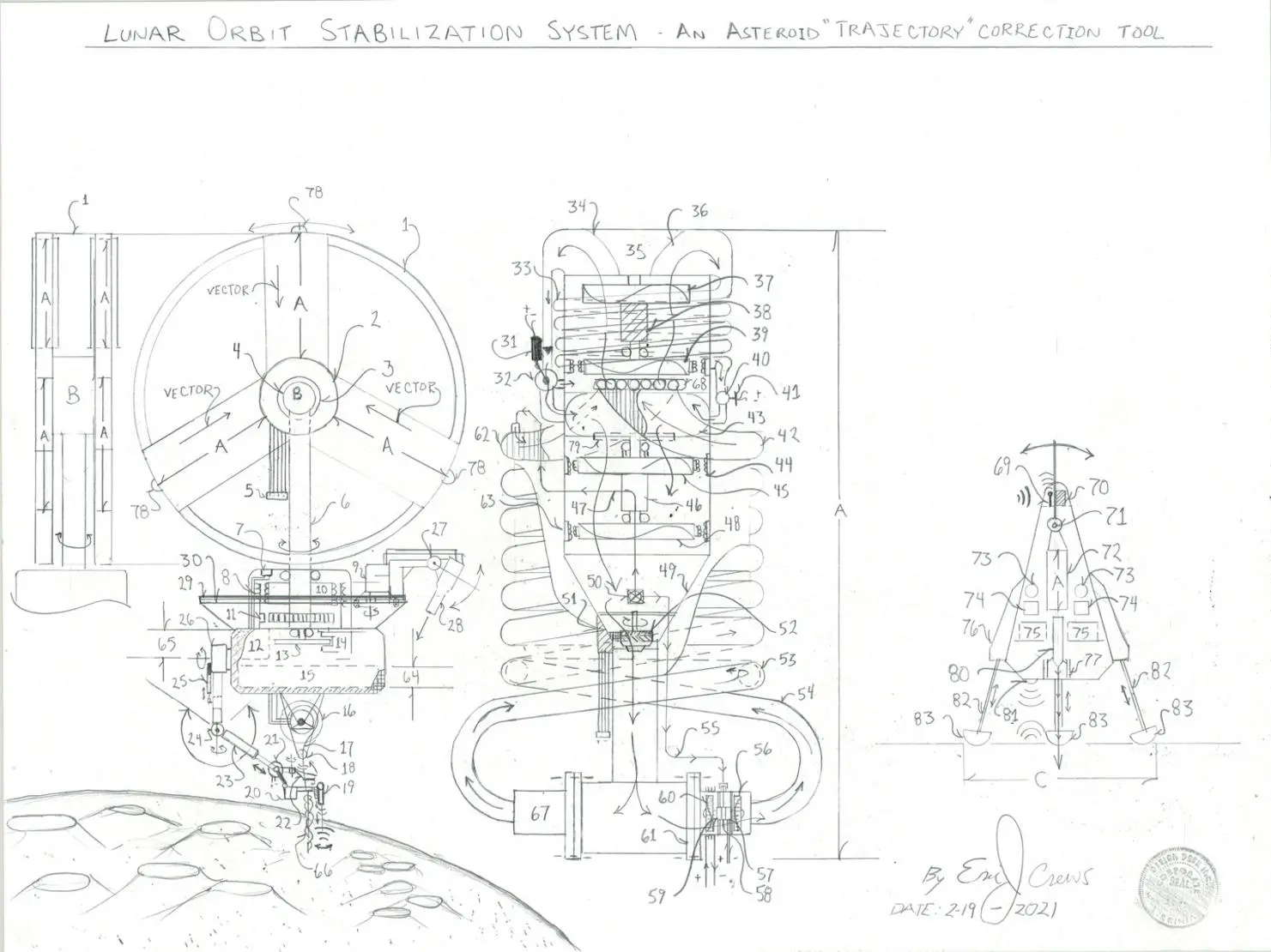
Parts List 1. motorized engine mounting “rotator ring” 2. engine mounting “hub” contains sealed bearing races and thru bore current (electrical) transfer “slip ring – multi track 3. rotator “ring” inverse electric motor (the field coil rotates the armature is stationary) 4. transmitter communications “Bay” to “allow” for spherical transmission of communications 5. multi wire wire”bus” ribbon wire connector encased within insulates and hazard projectile shock casing 6. center mounting rotator post “horizontal plane full rotation 360 degrees 7. ribbon wire docking receptacle 8. ribbon wire – multi wire 9. carbon dioxide laser power unit – fuel less high voltage production Ac current (alternating current) 10. horizontal plane center post armature of the drive electric motor 11. center rotating post position indicator sensor – aids in flight control 12. navigation / communications / electricity generator / engine control and thermal heating central core 13. center post disk break 14. center post disk break calipers (hydraulic pressure system actuated by electric solenoid) 15. high voltage generator “bay” contains cross-pump-generator within a noble gas pressurized chamber using argon or other suitable inert Noble Gas (non electrically conductive with plasma box static electricity dissipation to control unwanted electrical inductance) – feeds craft’s
system electricity 16. electric wench and heated carbon fiber insulated “rope” high tensile strength” 17. heater insulated carbon fiber “rope” 18. “rope” guide hoop 19. proximity sensor (radio) and primary melt bore to anchor the auger – spectrometer mass analyzer 20. shock casing shielded laser electronics and instrumentation for the radio proximity sensor 21. electric motorizes servo hinge 22. robotic clasp electric actuation (additional latch hoop upon the clasp fingers) 23. hydraulic piston upon the robotic “arm” 24. electric hinge servo 25. robotic arm hydraulic piston extender 26. 360 degree electric servo motor of the robotic arm 27. carbon dioxide laser servo “hinge” – electric motor with position sensor to then tilt the laser to cause the melt anchor circle of lunar Regolith 28. carbon dioxide laser (5000 degrees Celsius capacity) 29. carbon dioxide rotation track assembly – the laser is power motivated about 360 degrees about the horizontal plane to then melt the lunar Regolith in a disk shape to anchor the flight system 30. laser travel “track” thru bore current transfer slip ring 31. valve control solenoid 32. divergence valve changes the inert Noble Gas (Argon) flow direction 33. pneumatic perpendicular noble gas flow “coil” pipe 34. top assembly noble gas flow manifold 35. engine lamp system marker lamps and lamp electronics 36. top assembly noble gas flow manifold 37. noble gas impeller circumference electric motor 38. pressurized hydraulic draft accelerator speed incline system with hydraulic oil pressure ratio gear set counter tilt tandem rotating the the out put rotation of the units intern brush less electric drive motor that is the input rotation to the units 1:20 ratio gear set – internal hall effect r.p.m. (revolutions per minute) sensor reports to logic mapping circuits 39. high speed noble gas compressor propeller circumference brush less electricity generator voltage regulation in the engine control unit within number 12 – feeds electricity to the hyper jet electric
circumference motors number 44 40. noble gas one way gas fill valve with pressure sensor ( reports to logic mapping system control electronics),
and noble gas control unit…that “de-energizes” / controls unwanted electrical inductance. ie… controls static
electricity within the noble gas flow 41. electric noble gas “pressure sensor” information to the engine control logic electronic circuits 42. primary “return” noble gas flow pipe – perpendicular “return” off sets the force “static” in the force equation producing usable “sealed” direction thrust 43. noble gas collection “feed chamber” – feeds gas to the primary electric compound hyper sealed flow electric jet engine containing numbers 44, 46, and 48 44. high speed noble gas transonic compressor propeller and brush less circumference electric motor 45. hall effect r.p.m. (revolutions per minute) sensor 46. pressurized hydraulic draft accelerator speed incline system with hydraulic oil pressure ratio gear set counter tilt tandem rotating the the out put rotation of the units intern brush less electric drive motor that is the input rotation to the units 1:20 ratio gear set – internal hall effect r.p.m. (revolutions per minute) sensor reports to logic mapping circuits. Letter “A” internal jet fan compressor speed up upon their inert
Noble gas displacement to the remain in the engines operating service parameter. 47. main electric jet venturi decompression noble gas flow pipe – a venturi safety system to keep the venturi at correct operating pressure levels 48. noble gas impeller and electrical “generator” about the noble gas flow impeller circumference 49. noble gas compression venturi “funnel” 50. venturi safety valve – a dampener valve coil spring with electric solenoid force opening position should the p.s.i. (pounds per square inch) become excessive – the dampener valve contains an electric p.s.i. sensor reporting to the mapping logic electronic circuits 51. venturi “throttle” valve control unit 52. shutter valve / throttle valve adjustable noble gas flow 53. primary noble gas “return coil” flow pipe 54. primary noble gas “return coil” flow pipe 55. noble gas flow pipe feeds “pressure” to the vacuum electric that produces negative pressure in
the engine system 56. vacuum electric jet impeller circumference electric brush less electric motor 57. vacuum electric jet hall effect r.p.m. sensor – reports to the units logic mapping control electronic circuits 58. 1:10 ratio gear set high side tandem rotating with the vacuum jets “noble gas compressor number 60 59. thru bore electricity transfer slip ring 60. vacuum jet high speed “noble gas flow compressor” 61. union bolt plate – sum of 24 about 360 degrees equal spacing 62. noble gas return manifold 63. circumference “electrical” current “pick up” voltage regulation in the engine control unit within number 12 – feeds
electricity to the hyper jet electric circumference motors number 44 64. main generator bay contains 65. robotic “arm control bay” 66. carbon fiber “rope” anchor auger 67. vacuum electric jet same components and alignment mirror line to cause negative pressure post main venturi 68. top electric jet intake manifold 69. deep bore lander transmitter / receiver antenna 70. communications electronics 71. motorized engine “hinge” 72. electric hyper jet assemble same as letter labeled as letter “A” 73. landing gear hydraulic systems 74. laser control systems 75. craft generator bay “sealed chamber 76. landing gear “bay” 77. insulated laser guide chamber 78. marker / work lamp 79. thrust / pressure port 80. main carbon dioxide laser 81. surface proximity sensor 82. landing gear 83. landing “foot”
Letter “A” = sealed force vector electric hyper jet
Letter “B” = hub rotator electric positioning system (servo) contains position sensor to assist navigation
Letter “C” = deep bore lander – melts angled bore in Regolith to assist in anchoring the Regolith anchor disk Description The flight system will melt a bore into the Regolith to then “sink” the auger and let the bore cool… then the main carbon dioxide laser, number 28 will melt the Regolith in a circular format to produce a homogeneous “disk” to act as the lift system anchor. The unit labeled letter “C” then landing upon the disk to deep bore melt angled retainers to increase the disk stability. The six engine lift craft will then ascend to zero gravity with the anchor tethered and apply the thrust required to in time stabilize the moon’s escape. Multiple craft required to obtain the objective.​
The total system is then of multitude of craft about the total circumference of the moon as per required to then stabilize the moon’s escape. The system makes a circular melt by carbon dioxide laser to a depth of 12″ – 18″ with the circular disk then 18′ to 36′ diameter circle with letter “C” then landing atop the melt circle to produce an anchor lock / deep melt angular shape. The tether then 50 miles with twice the rated max tensile strength rated for the low temperature of outer space. It may not be required to full extend the tether but the length required to then be able to be used in other application such as neo / asteroid mitigation. This design system is required due to the moon escaping it’s Earth locked orbit factoring the effects of orbital elongation (perigee, apogee, Apsis) over long time spans… factoring equatorial atmospheric altitude increase due to global warming , earth spin rate, Earth and lunar gravity factoring type of atmospheric gas (water vapor Ch4 methane , CO2) and the projected trends due to infrastructure and population. The lunar “escape” ( temporal “procession”), “perigee” then causes a closer proximity to Earth’s high altitude atmosphere. Global warming then adding mass to the high altitude atmosphere due to increased water uptake causing a center point offset gravity increase. It’s slight but occurring. The moon’s orbit is elliptical not circular. Factoring the off set Earth center of gravity due to increased cloud water vapor formation due to climate change also changes the Earth’s gravimetric center point. The Apsis in the escape trajectory causing closer proximity to the earth in its orbital cycle. Gravity “changes with density” or loss there of…. Is Earth bleeding Ozone into outer space due to heating and lunar orbit effecting the equatorial Ozone layer?… lowering the altitude at it’s poles? The moon’s escape is slow… effecting Earth’s climate slightly… an “aspect” of Climate Change factoring sea level rise and the fluid nature of atmosphere (tides in the skies). Granted the approximate one and one half inch per year is a small distance but the rate of orbital deformation can change with other advent such as lunar asteroid / comet impact. The design can be modified with electromagnetic field “bearings” in lieu of standard sealed bearings for long running.
The multitude of craft then of light weight low cost construction using a blend cold temperature plastic carbon graphite and non metal electrical conductive in lieu of motor wire, to lessen the cost. The components then derived from systems such as
solar-assist-carbon-dioxide-sequestration-system
*