
Motivator
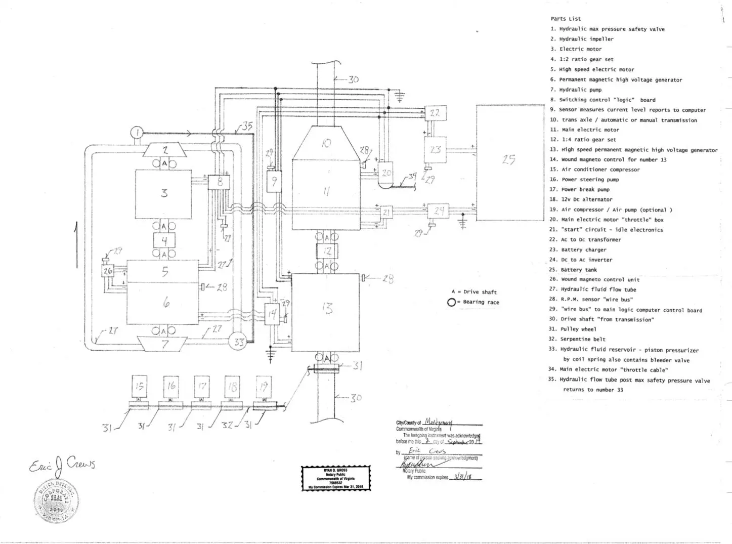
The “Motivator is an electric automobile motor system that will have unlimited range and will self charge. Parts List 1. Hydraulic max pressure safety valve 2. Hydraulic impeller 3. Electric motor 4. 1:2 ratio gear set 5. High speed electric motor 6. Permanent magnetic high voltage generator 7. Hydraulic pump 8. Switching control “logic” board 9. Sensor measures current level reports to computer 10. trans axle / automatic or manual transmission 11. Main electric motor 12. 1:4 ratio gear set 13. High speed permanent magnetic high voltage generator 14. Wound magneto control for number 13 15. Air conditioner compressor 16. Power steering pump 17. Power break pump 18. 12v Dc alternator 19. Air compressor / Air pump (optional ) 20. Main electric motor “throttle” box 21. “start” circuit – idle electronics 22. Ac to Dc transformer 23. Battery charger 24. Dc to Ac inverter 25. Battery tank 26. Wound magneto control unit 27. Hydraulic fluid flow tube 28. R.P.M. sensor “wire bus” 29. “wire bus” to main logic computer control board 30. Drive shaft “from transmission” 31. Pulley wheel 32. Serpentine belt 33. Hydraulic fluid reservoir – piston pressurizer by coil spring also contains bleeder valve 34. Main electric motor “throttle cable” 35. Hydraulic flow tube post max safety pressure valve returns to number 33 Description: From “Start” current in number 25, The Dc to Ac inverter in number 24 will energize numbers 11, 5 and 3. This causes rotation to “base idle”. With number 3 rotating into the 1:2 ratio gear set number 4’s rotational out put is twice that of input rotational speed. Number 5 then is reducing the resistance produced in the gear set and counteracts the resistance produced by the pumping of the hydraulic fluid. The fluid speed is then impaling an impeller attached to the drive shaft that is attached to number 3 causing it to speed up. This part of the system is circular and will increase in speed compounding rotation. The current produced in number 6 then feeds number 13’s field coil and branches into number 20 and then to number 11. The current intensity to number 11 is always greater than the current intensity to number 13 to allow the system to climb in rotational speed. Number 13’s electrical output is fed to number 8 then numbers 3 and 5 causing rotational increase and more current produced. Number 13’s electrical output is also fed to number 20 and then to number 11 causing the whole system to accelerate. The system is “load reactive”. Number 6 also energizes an Ac to Dc transformer and then powers a battery charger to then charge the battery when the system is in operation. The “start” circuit is the in the off position when in operation. Number 11 causes number 13 to rotate at four times the rotational velocity because of the ratio gear set number 12. Both drive shafts number 30 are connected to number 10 (trans-axle/ transmission). The field coil intensity for numbers 6 and 13 are adjustable and will increase in intensity at high rotational speed.